SC200 Single Loop Controller Series
MULTI-FUNCTION PID CONTROLLER
(color LCD with touch-panel, Modbus/NestBus communication)
MODEL: SC200–[1][2]–[3][4]
ORDERING INFORMATION
• Code number: SC200-[1][2]-[3][4]
Specify a code from below for each [1] through [4].
(e.g. SC200-11-M2/3/E/1/T/Q)
• Specify the specification for option code /Q
(e.g. /C01/S01)
[1] DISCRETE OUTPUT
1: Relay contact
2: Photo MOSFET relay
[2] MODBUS
1: Modbus-RTU
2: Modbus/TCP
[3] POWER INPUT
AC Power
M2: 100 – 240 V AC (Operational voltage range 85 – 264 V, 50/60 Hz)
DC Power
R: 24 V DC
(Operational voltage range 24 V ±10 %, ripple 10 %p-p max.)
[4] OPTIONS (multiple selections)
Housing Depth
blank: 250 mm
/300: 300 mm (Discontinued, select /3)
/400: 400 mm (Discontinued, select /4)
/3: 300 mm
/4: 400 mm
Language
blank: Japanese
/E: English
(Language (Japanese or English) can be chosen by front
panel setting.)
Configurator Interface
blank: Infrared
/1: Stereo jack
(If external noise interference is a concern, stereo jack
type is recommended.)
Terminal block
blank: One block terminal
/T: Separable terminal
Other Options
blank: none
/Q: Option other than the above (specify the specification)
SPECIFICATIONS OF OPTION: Q (multiple selections)
COATING (For the detail, refer to M-System's web site.)
/C01: Silicone coating
/C02: Polyurethane coating
/C03: Rubber coating
TERMINAL SCREW MATERIAL
/S01: Stainless steel
FUNCTIONS & FEATURES
Functions & Features
• Color LCD with touch panel
• Five Operation views (digital display, bargraph, dual-loop bargraph, short trend and user's parameter table views)
• Enhanced screen functions for engineering (configuration, programming and tuning views)
• Universal input x 2 points, analog input x 4 points, discrete input x 6 points, pulse input x 5 points, high speed pulse input x 1 point
• Current output (4-20 mA) x 2 points, voltage output (1-5 V) x 2 points, relay or photo-MOSFET relay output x 5 points
• RUN contact output (relay) x 1 point
• I/O signals can be added with remote I/O modules connected via NestBus peer-to-peer communication
• Computation cycle selectable between 50 msec. and 3 sec. (control cycle selectable between 1 and 64 times of the computation cycle)
• Two PID function blocks
• Advanced computation and sequence control functions
• Auto-tuning function
• Parameter input and changing with touch panel
• Function parameter setting, list printing and data downloading/uploading available with Loop Configuration Builder Software (model: SFEW3E)
• Short trend export (CSV), display parameter setting, saving and transfer with PC Configurator Software (model: SCCFG)
• Control and supervision by SCADA software via Modbus TCP/IP or RTU communication
• Selectable housing depth for ease of using existing wires in replacement: 250 mm, 300 mm and 400 mm
• Separable terminal block
Typical Applications
• Replacement of conventional controllers
• Panel operation for small-scale instrumentation
RELATED PRODUCTS
• PC Configurator cable (model: COP-US)
• Loop configuration builder software (model: SFEW3E Ver. 1.40 or later)
• Infrared communication adaptor (model: COP-IRDA)
• PC configurator software (model: SCCFG Ver.1.50 or later)
Builder software and configurator software are downloadable at M-System’s web site.
ACCESSORIES
• Precision resistor module (model: REM4): 2
• Cold junction sensor: 2
• Mounting brackets: 2
• Connector adapter: 1
(included in Stereo jack type. The jack on the unit and the plug of PC Configurator cable (not included in the product) are different in size.)
GENERAL SPECIFICATIONS
Construction: Panel flush mounting
Degree of protection: IP55; ensured for the front panel of the unit independently mounted to a panel
Connection
Terminal screws: M3.5 screw terminals (torque 1.0 N·m)
Terminal fixing screws: M4 screw terminals
(torque 1.2 N·m)
Ethernet: RJ-45 Modular Jack
Screw terminal
Terminal screws: Nickel-plated steel (standard) or stainless steel
Terminal fixing screws: Chrome-plated steel
Housing material: Flame-resistant resin (gray), steel
Isolation: Pv1 to Pv2 to supply output to Ai1 or Ai2 or Ai3 or Ai4 to Di1 or Di2 or Di3 or Di4 or Di5 or Pi1 or Pi2 or Pi3 or Pi4 or Pi5 to Di6 or Pi6 to Mv1 to Mv2 to Ao1 or Ao2 to Do1 to Do2 to Do3 to Do4 to Do5 to Do6 to NestBus to Modbus-RTU to Modbus/TCP to power to FG
PID control: Single loop, cascade, advanced
・Proportional band (P): 1 to 1000 %
・Integral time (I): 0.01 to 100 minutes
・Derivative time (D): 0.01 to 10 minutes
Auto-tuning: Limit cycle method
Alarm: PV high & low, deviation, rate of change
Computation: 48 functions blocks available for arithmetic operations, time functions, signal selection, limit, alarm and other functions
Sequence operation: Logic sequence and step sequence (max. 1068 commands)
Computation cycle: 50 msec. to 3 sec. (control cycle selectable among 1, 2, 4, 8, 16, 32 and 64 times of the computation cycle)
MV output range: -15 - +115 %
Parameter setting: With touch panel or PC (Loop Configuration Builder Software model: SFEW3E)
Self diagnostics: CPU monitoring with a watchdog timer
RUN contact: OFF in error detected by diagnostic (including NestBus)
Infrared communication: Transmission distance max. 0.2 meter (for use with the COP-IRDA)
Short trend
Storing interval: 1, 2, 5, 10, 20, 30 sec.,
1, 2, 5, 10, 30, 60 min.
Capacity: 400 points (display 200 points)
■ Display
Display device: 4.3-inch TFT LCD
Display colors: 256
Resolution: 480 × 272 pixels
Pixel pitch: 0.198 × 0.198 mm (128 × 128 DPI)
Backlight: LED
Backlight life: Approx. 50 000 hours (at 50 % brightness)
Note: The backlight can be replaced in M-System factory.
The LCD must be replaced at the same time.
Screen saver standby time: 1 to 99 minutes
Scaling range: -32000 to +32000
Decimal point position: 10-1, 10-2, 10-3, 10-4, 10-5 or none
Scale divisions: 2 to 10
Engineering unit indication: Max. 8 characters
Auto/Man indicator: Green/Amber LED
FACTORY DEFAULT
EXTERNAL INTERFACE
■ NestBus
Configuration: Bus type multi-drop
Standard: Conforms to TIA/EIA-485-A
Transfer rate: 19.2 kbps
Protocol: NestBus (M-System’s own protocol)
Max. transmission distance: 1 kilometer
Transmission media:
Shielded twisted-pair cable (CPEV-S 0.9 dia.)
Terminating resistor: incorporated
Address setting: 0 - F (16 nodes)
■ Modbus-RTU
Configuration: Half-duplex, asynchronous, no procedure
Standard: Conforms to TIA/EIA-485-A
Max. transmission distance: 500 meters
Transfer rate: 4800, 9600, 19.2 k, 38.4 k bps
Data bit: 8
Parity bit: Odd, even, none
Max. node number: 15 (except the master)
Transmission media:
Shielded twisted-pair cable (CPEV-S 0.9 dia.)
Terminating resistor: incorporated
Node address setting: 1 - 247
■ Modbus/TCP (Ethernet)
Physical layer standard: IEEE 802.3u
Data link layer: 10BASE-T / 100BASE-TX
Transfer rate: 10 / 100 Mbps, Auto Negotiation
Protocol: Modbus/TCP
Data: RTU (binary)
Connections: 2
Transmission media:
10BASE-T (STP cable, category 5)
100BASE-TX (STP cable, category 5e)
Max. segment length: 100 meters
Port number: 502
IP address: 192.168.0.1 (factory setting)
SUPPLY OUTPUT
Output voltage:
24 V DC ±10 % with no load
18 V DC min. at 20 mA
Current rating: ≤ 22 mA DC
∙Shortcircuit protection
Current limited: Approx. 30 mA
INPUT SPECIFICATIONS
■ Pv1, Pv2 (universal input)
∙Current input: 4 – 20 mA DC with input resistance 250 Ω (REM4)
∙Voltage input: -10 – +10 V DC
-1 – +1 V DC
0 – 10 V DC
1 – 5 V DC
0 – 1 V DC
Input resistance: ≥ 1 MΩ
∙Thermocouple input: K, E, J, T, B, R, S, C, N, U, L, P, PR (See Table 1)
Input resistance: ≥ 30 kΩ
Burnout sensing: ≤ 0.3 µA
Burnout indication: 115 % of the measuring range (upscale)
∙RTD input: Pt100 (JIS ’97, IEC), Pt100 (JIS ’89), JPt100 (JIS ’89), Pt50Ω (JIS ’81), Ni100 (See Table 2)
Maximum lead wire resistance: 100 Ω per wire
Burnout indication: 115 % of the measuring range (upscale)
Sensing current: ≤ 1 mA
∙Potentiometer input: Total resistance 100 Ω to 10 kΩ
Minimum span: 50 % of total resistance
Excitation: ≤ 0.6 V DC
■ Ai1, Ai2, Ai3, Ai4
∙Voltage input: 1 – 5 V DC
Input resistance: ≥ 1 MΩ
■ Pi1, Pi2, Pi3, Pi4, Pi5: Dry contact
(Di1 through Di5 are assigned to the same terminals respectively.)
Maximum frequency: 20 Hz
Minimum pulse width: 25 msec.
Common: Negative common per 5 points
Sensing: Approx. 12 V DC, 6 mA
ON voltage/resistance: ≤ 2.25 V, ≤ 1.5 kΩ
OFF voltage/resistance: ≥ 11.25 V ≥ 15 kΩ
■ Pi6: Dry contact
(Di6 is assigned to the same terminal.)
Maximum frequency: 10 kHz
Minimum pulse width: 0.05 msec.
Common: Negative common
Sensing: Approx. 12 V DC, 12 mA
ON voltage/resistance: ≤ 2 V, ≤ 1.5 kΩ
OFF voltage/resistance: ≥ 11 V, ≥ 15 kΩ
Excitation: 12 V DC ±10%, 15 mA
Current limiting circuit: Approx. 30 mA
■ Di1, Di2, Di3, Di4, Di5: Dry contact
(Pi1 through Pi5 are assigned to the same terminals respectively.)
Common: Negative common per 5 points
Sensing: Approx. 12 V DC, 6 mA
ON voltage/resistance: ≤ 2.25 V, ≤ 1.5 kΩ
OFF voltage/resistance: ≥ 11.25 V ≥ 15 kΩ
■ Di6: Dry contact
(Pi6 is assigned to the same terminal.)
Common: Negative common
Sensing: Approx. 12 V DC, 12 mA
ON voltage/resistance: ≤ 2 V, ≤ 1.5 kΩ
OFF voltage/resistance: ≥ 11 V, ≥ 15 kΩ
OUTPUT SPECIFICATIONS
■ Mv1, Mv2
∙Current output: 4 – 20 mA DC
Load resistance: ≤ 600 Ω
■ Ao1, Ao2
∙Voltage output: 1 – 5 V DC
Load resistance: ≥ 10 kΩ
■ Discrete Output
∙Do1, Do2, Do3, Do4, Do5, RUN contact (Do6): Relay contact
Rated load: 250 V AC @1 A (cos ø = 1)
30 V DC @1 A (resistive load)
Maximum switching voltage: 250 V AC or 30 V DC
Maximum switching power: 250 VA or 60 W
Minimum load: 5 V DC @10 mA
Mechanical life: 2 × 10⁷ cycles
∙Do1, Do2, Do3, Do4, Do5: Photo MOSFET relay
Rating: 200 V AC/DC @0.5 A (resistive load)
ON resistance: 2.1 Ω
Maximum frequency: 4 Hz @24 V, 10 mA
ON delay time: ≤ 5.0 msec.
OFF delay time: ≤ 3.0 msec.
INSTALLATION
Power input
∙AC:
≤ 25 VA at 100 V AC
≤ 40 VA at 240 V AC
•DC: ≤ 650 mA
Operating temperature: -5 to +55°C (23 to 131°F)
Operating humidity: 5 to 90 %RH (non-condensing)
Mounting: Panel flush mounting (high-density mounting in horizontal direction)
Weight:
Approx. 1.8 kg (3.97 lb) for 250 mm depth type
Approx. 2.0 kg (4.41 lb) for 300 mm depth type
Approx. 2.5 kg (5.51 lb) for 400 mm depth type
PERFORMANCE
Accuracy
DC input: ±0.1 % ±1 digit
Thermocouple input: ±1℃ ±1 digit
±2℃ ±1 digit for B, R, S, C and PR
RTD input: ±1℃ ±1 digit
Potentiometer input: ±0.2 % ±1 digit
DC output: ±0.1 %
Precision resistor module (REM4): ±0.1 %
Cold junction compensation:
±2°C at 25°C ±10°C
±4°C for S, R and PR
Temp. coefficient: ±0.015 %/°C (±0.008 %/°F)
DC input: ±0.015 %/°C (±0.008 %/°F)
Thermocouple input: ±0.015 %/°C (±0.008 %/°F)
RTD input: ±0.015 %/°C (±0.008 %/°F)
Potentiometer input: ±0.015 %/°C (±0.008 %/°F)
DC output: ±0.015 %/°C (±0.008 %/°F)
Precision resistor module (REM4): ±0.015 %/°C (±0.008 %/°F)
Line voltage effect: ±0.1 % over voltage range
Calendar clock accuracy: Monthly deviation 3 minutes at 25°C
RAM memory duration in power failure for hot start:
10 minutes assured
Insulation resistance: ≥ 100 MΩ with 500 V DC
Dielectric strength:
1500 V AC @ 1 minute
(Pv1 or supply output to Pv2 or Ai1 or Ai2 or Ai3 or Ai4 to Di1 or Di2 or Di3 or Di4 or Di5 or Pi1 or Pi2 or Pi3 or Pi4 or Pi5 to Di6 or Pi6 to Mv1 to Mv2 or Ao1 or Ao2 to Do1 to Do2 or Do3 or Do4 or Do5 or Do6 to NestBus to Modbus-RTU to Modbus/TCP to power to FG)
500 V AC @ 1 minute (Pv2 to Ai1 or Ai2 or Ai3 or Ai4)
500 V AC @ 1 minute (Mv2 to Ao1 or Ao2)
500 V AC @ 1 minute (Do2 to Do3 to Do4 to Do5 to Do6)
500 V AC @ 1 minute (Pv1 to supply output)
STANDARDS & APPROVALS
EU conformity:
EMC Directive
EMI EN 61000-6-4
EMS EN 61000-6-2
Low Voltage Directive
EN 61010-1
Measurement Category II (contact output)
Installation Category II (power)
Pollution degree 2
Input or output to contact output – Basic insulation (300 V)
Input or output to power - Reinforced insulation (300 V)
RoHS Directive
EN 50581
Protection against access to the terminal blocks:
Finger protection (VDE 0660-514)
EXTERNAL VIEW
COMMUNICATION CABLE CONNECTIONS
EXTERNAL DIMENSIONS & TERMINAL ASSIGNMENTS unit: mm (inch)
MOUNTING REQUIREMENTS unit: mm
■ Caution
• IP55 is ensured for the front panel of the unit mounted independently according to a panel. Test the sealing at the mounting surface once the device is installed.
• Set the unit on a vertical surface with its operation buttons at the lower side. Mounting in other directions may cause heat built up inside the unit and shorten its life span or degrade its performance.
• Ensure that there is sufficient space for ventilation inside a panel. Do not install above the devices that generate high heat such as heaters, transformers or resistors. Leave at least 30 mm (1.2 inch) space above, below and behind the unit for maintenance purpose (e.g. wiring, removing or installing).
SCHEMATIC CIRCUITRY & CONNECTION DIAGRAM
Note: In order to improve EMC performance, bond the FG terminal to ground.
Caution: FG terminal is NOT a protective conductor terminal.
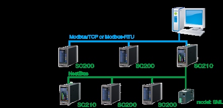
SYSTEM CONFIGURATION EXAMPLES
M-System Vietnam Email: sales@m-system.com.vn
|