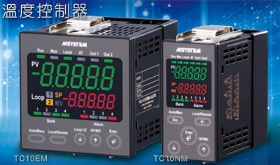
TC10NM Temperature Controller TC10 Series
TEMPERATURE CONTROLLER
(Modbus, 5 digit, LED display type, size 48 x 96 mm)
Functions & Features
• One PID controller
• Universal input x 1 point, control output x 4 points, discrete input x 2 points, clamp-on current sensor input x 1 point
• Universal input configurable to T/C, RTD, DC current or voltage independently
• Discrete inputs usable to switch PID bank or operation mode
• Control outputs configurable to MV, PV or alarm
• Clamp-on current sensor input enables to detect heater wire break or over current
• Auto tuning function
MODEL: TC10NM–[1]–M2
ORDERING INFORMATION
• Code number: TC10NM-[1]-M2
Specify a code from below for [1].
(e.g. TC10NM-A-M2)
[1] CONTROL OUTPUT
A: 0 – 20 mA DC (Load resistance 500 Ω max.)
Open-collector 2 points
V: 0 – 10 V DC (Load resistance 2 kΩ max.)
Open-collector 2 points
P: 12 V pulse (Load resistance 600 Ω max.)
Open-collector 2 points
POWER INPUT
AC Power
M2: 100 – 240 V AC (Operational voltage range 85 – 264 V,
47 – 66 Hz)
RELATED PRODUCTS
• PC configurator software (model: TC10CFG)
Downloadable at M-System’s web site.
A dedicated cable is required to connect the module to the PC. Please refer to the internet software download site or the users manual for the PC configurator for applicable cable types.
• Clamp-on current sensor (model: CLSE)
(Used for detecting the heater wire break)
GENERAL SPECIFICATIONS
Construction: Panel flush mounting
Degree of protection: IP65; applicable to the front panel of the unit with single mounting according to the specified panel cutout
Configuration jack: 2.5 dia. miniature jack connector;
RS-232-C level (bottom of the unit)
Connection: M3 separable screw terminal (torque 0.5 N·m)
Solderless terminal: Refer to the drawing at the end of the section.
Recommended manufacturer: Japan Solderless Terminal MFG.Co.Ltd, Nichifu Co.,ltd
Applicable wire size: 0.25 to 1.65 mm2 (AWG 22 to 16)
Screw terminal: Nickel-plated steel
Housing material: Flame-resistant resin (gray)
Isolation: Pv1 to CT1 to Di1 or Di2 to MV1 to MV2 to Do1 or Do2 to Modbus to power
CT Input waveform
RMS sensing: Up to 15 % of 3rd harmonic content
Control mode: Standard PID, heating and cooling control (ON/OFF, PID)
・Proportional band (P): 0.1 to 3200.0 (temperature unit)
・Integral time (I): 0 to 3999 sec.
・Derivative time (D): 0.0 to 999.9 sec.
Auto-tuning: Limit cycle method
Alarm: Deviation high & low, absolute high & low, etc.
Sampling cycle: 100 msec.
Control cycle: 1.0 to 99.9 sec.
(100 msec. fixed for Mv output 0 - 20 mA DC
and 0 - 10 V DC)
Mv output range: -5 - +105 % for output scale
Parameters: Stored in non-volatile memory; write/erase cycle endurance: less than 1 000 000
Parameter setting: With front panel operation buttons or PC configurator software (model: TC10CFG)
• Universal input
• Burnout on/off
• Control output
• Bank
• Event input
• CT input
• Auto-tuning
Refer to the instruction manual for detail.
MODBUS COMMUNICATION
Communication: Half-duplex, asynchronous, no procedure
Standard: Conforms to TIA/EIA-485-A
Transmission distance: 500 meters max.
Transmission media: Shielded twisted-pair cable
(CPEV-S 0.9 dia.)
Node adress: 1 to 247
Data mode: RTU (Binary)
Parity: None, even or odd
Baud rate: 4800, 9600, 19.2 k, 38.4 k, 57.6 k (bps)
Stop bit: 1 or 2
Node adress, parity, baud rate setting: With front panel operation buttons or PC configurator software (model: TC10CFG)
Terminating resistor: Built-in (Enable by shorting between pin 3 and 4)
DISPLAY
PV display: 5 digits 7-segment green LED, 10.2 mm (.40”) height
SP display: 5 digits 7-segment red LED, 8.2 mm (.32”) height, switchable to MV display
Display range: -32000 to 32000
Decimal point position: 10–1 to 10–4 or none
Zero indication: Higher-digit zeros are suppressed.
Loop status indicators
Bank1: Green LED turns on when bank 1 chosen
Bank2: Green LED turns on when bank 2 chosen
Bank3: Green LED turns on when bank 3 chosen
Bank4: Green LED turns on when bank 4 chosen
Alarm1: Red LED turns on at alarm 1
Alarm2: Red LED turns on at alarm 2
Alarm3: Red LED turns on at alarm 3
Alarm4: Red LED turns on while setting is saving to the non-volatile memory.
Run: Green LED turns on while loop is in operation.
Man: Green LED turns on during manual mode
Local: Unused, off
At: Green LED turns on during auto-tuning
Out1: Green LED turns on when MV1 output
Out2: Green LED turns on when MV2 output
Engineering unit indication: Sticker label attached
DC, AC, mV, V, kV, μA, mA, A, kA, mW, W,
kW, var, kvar, Mvar, VA, Hz, Ω, kΩ, MΩ,
cm, mm, m, m/sec, mm/min, cm/min, m/min,
m/h, m/s2, inch, ℓ, ℓ/s, ℓ/min, ℓ/h, m3, m3/sec,
m3/min, m3/h, Nm3/h, N·m, N/m2, g, kg, kg/h,
N, kN, Pa, kPa, MPa, t, t/h, ℃, °F, %RH, J,
kJ, MJ, rpm, sec, min, min-1, pH, %, ppm, etc.
INPUT SPECIFICATIONS
■ Universal input (Pv1)
For type and range configuration, refer to the instruction
manual.
・DC Current:
Input range: 0 - 20 mA DC
Input resistance: 49.9 Ω resistor incorporated
• DC voltage input
Input resistance: ≥ 10 kΩ (-1000 to +1000 mV DC)
Input resistance: ≥ 1 MΩ (-10 to +10 V DC)
• Thermocouple
Input resistance: ≥ 10 kΩ
Input range: Refer to the table 1
Burnout sensing: ≤ 4 μA
Conformance range: Refer to the table 1
• RTD (2-wire or 3-wire)
Excitation: ≤ 0.33 mA
Input range: Refer to the table 1
Allowable leadwire resistance: 20 Ω per wire
• Resistor (2-wire or 3-wire)
Excitation: ≤ 0.33 mA
Input range: 0 - 4000 Ω
Allowable leadwire resistance: 20 Ω per wire
• Potentiometer
Excitation: ≤ 0.33 mA
Input range: 0 to 4000 Ω
Allowable leadwire resistance: 20 Ω per wire
■ Clamp-on current sensor (CT1)
(Sensor model No.: AC input)
CLSE-R5: 0 – 5 A
CLSE-05: 0 – 50 A
CLSE-10: 0 – 100 A
CLSE-20: 0 – 200 A
CLSE-40: 0 – 400 A
CLSE-60: 0 – 600 A
Frequency: 50 / 60 Hz (45 - 65 Hz)
Max. working voltage: 480 V AC (primary side)
Overload capacity:
CLSE-R5: 10 A continuous, x40 (1 sec.)
CLSE-05: 60 A continuous, x40 (1 sec.)
CLSE-10: 120 A continuous, x40 (1 sec.)
CLSE-20: 240 A continuous, x40 (1 sec.)
CLSE-40: 480 A continuous, x40 (1 sec.)
CLSE-60: 720 A continuous, x40 (1 sec.)
Operational range
CLSE-R5: ≤ 5 A
CLSE-05: ≤ 50 A
CLSE-10: ≤ 100 A
CLSE-20: ≤ 200 A
CLSE-40: ≤ 400 A
CLSE-60: ≤ 600 A
Caution 1: The output values may vary depending on the accuracy of engagement at the clamp connection.
Caution 2: The sensor’s mechanical construction may cause it to generate resonance sound. However, it does not affect the perfomrance of the sensor.
■ Discrete Input (Di1, Di2)
Contact rating: 3.3 V @ 0.33 mA
Detection levels:
≤ 1.6 kΩ / 0.5 V at close
≥ 30 kΩ / 2.5 V at open
OUTPUT SPECIFICATIONS
Four control outputs are configurable to Mv, Ao or Do.
■ Control Output (Mv1, Mv2)
Specify one type of output with the code number from 3 types shown below.
• DC Current: 0 – 20 mA DC
Operational range: 0 – 23 mA DC
Load resistance: ≤ 500 Ω
• DC Voltage: 0 – 10 V DC
Operational range: 0 - 11.5 V DC
Load resistance: ≥ 2 kΩ
• 12 V Voltage pulse
Maximum frequency: 1 Hz
Minimum pulse width: 1 msec.
Hi level: 12 V ±15 %
Lo level: ≤ 0.5 V
Load resistance: 600 Ω min.
■ Control Output (Do1, Do2)
• Open collector
Maximum frequency: 1 Hz
Minimum pulse width: 1 msec.
Output rating: 50 V DC 100 mA (resistive load)
Saturation voltage: 0.5 V DC
INSTALLATION
Power Consumption
•AC:
Approx. 6 VA at 100 V
Approx. 7 VA at 200 V
Approx. 8 VA at 240 V
Operating temperature: -10 to +55°C (14 to 131°F)
Operating humidity: 5 to 90 %RH (non-condensing)
Atmosphere: No corrosive gas or heavy dust
Mounting: Panel flush mounting
Weight: 300 g (0.66 lb)
PERFORMANCE in percentage of span
Accuracy
• Pv1: Refer to "Input type, range & conversion accuracy" section.
• CT1: ±2 % (sensor error margin not included)
• MV1 or MV2: ±0.5 % (added to the input accuracy)
Cold junction compensation error (thermocouple input):
±2.0°C at -10 – 55°C (±3.6°F at 14 – 131°F)
CJC sensor is adjacently attached to the input terminals.
Temp. coefficient
• Pv1: ±0.03 %/°C (± 0.02 %/°F)
• CT1: ±0.03 %/°C (± 0.02 %/°F)
Response time
• CT1: ≤ 2 sec. (0 – 90 %)
• Mv1 or Mv2: ≤ 1 sec. (0 – 90 %, DC output)
Burnout response (thermocouple, RTD, resistor, potentiometer input): ≤ 10 s
Insulation resistance: ≥ 100 MΩ with 500 V DC
Dielectric strength: 2000 V AC @1 minute (Pv1 to CT1 to Di1 or Di2 to MV1 to MV2 to Do1 or Do2 to Modbus to power to ground)
STANDARDS & APPROVALS
EU conformity:
EMC Directive
EMI EN 61000-6-4
EMS EN 61000-6-2
Low Voltage Directive
EN 61010-1
Installation Category II
Pollution Degree 2
Input or output or Modbus to power – Reinforced insulation (300 V)
Input to output to Modbus – Basic insulation (300 V)
RoHS Directive
EN 50581
INPUT TYPE, RANGE & CONVERSION ACCURACY
EXTERNAL VIEW
COMMUNICATION CABLE CONNECTIONS
EXTERNAL DIMENSIONS & TERMINAL ASSIGNMENTS unit: mm (inch)
SCHEMATIC CIRCUITRY & CONNECTION DIAGRAM
M-System Vietnam Email: sales@m-system.com.vn
|