48NDT BARGRAPH INDICATING ALARM (with 4-digit digital meter; thermocouple input)
Functions & Features • Displays a process variable in graphic bargraph of 101 LED segments • Clear 4-digit digital meter • Provides max. 4 alarm contact outputs • Multi-color indicator • Linearization and burnout • LED brightness adjustment • IP65 front cover • Scale plate is easily replaced • Separable terminal block
MODEL: 48NDT–[1][2][3]–[4][5]
ORDERING INFORMATION • Code number: 48NDT-[1][2][3]-[4][5] Specify a code from below for each of [1] through [5]. (e.g. 48NDT-422-R/CE/D/BL/Q) • Temperature range (e.g. 0 – 500 °C) • Bargraph scale (e.g. 0 – 100 %) (See ‘Scale Plate.’) • Digital indicator scale (e.g. 0.0 – 500.0) • Specify the specification for option code /Q (e.g. /C01/SET)
[1] ALARM OUTPUT 0: None 2: 2 points 4: 4 points
[2] BAR LED COLOR R: Red Y: Amber G: Green B: Blue 1: Multi-color (red, orange and green), Pattern 1 (See ‘External View.’) 2: Multi-color (red, orange and green), Pattern 2 (See ‘External View.’)
[3] INPUT THERMOCOUPLE 1: (PR) (Usable Range 0 to 1760°C, 32 to 3200°F) 2: K (CA) (Usable range -270 to +1370°C, -454 to +2498°F) 3: E (CRC) (Usable range -270 to +1000°C, -454 to +1832°F) 4: J (IC) (Usable range -210 to +1200°C, -346 to +2192°F) 5: T (CC) (Usable range -270 to +400°C, -454 to +752°F) 6: B (RH) (Usable range 0 to 1820°C, 32 to 3308°F) 7: R (Usable range -50 to +1760°C, -58 to +3200°F) 8: S (Usable range -50 to +1760°C, -58 to +3200°F) N: N (Usable range -270 to +1300°C, -454 to +2372°F)
[4] POWER INPUT AC Power M: 85 – 264 V AC (Operational voltage range 85 – 264 V, 50/60 Hz) (CE marking not available) M2: 100 – 240 V AC (Operational voltage range 85 – 264 V, 50/60 Hz) DC Power R: 24 V DC (Operational voltage range 24 V ±15 %, ripple 10 %p-p max.)
[5] OPTIONS (multiple selections) Standards & Approvals blank: Without CE /CE: CE marking Bezels blank: Bezels for M-System’s 48 Series panel cutout /D: Bezels for DIN panel cutout /F: Bezels for Fuji Electric's PAJ, PAK, PBA panel cutout Burnout blank: Upscale burnout /BL: Downscale burnout /BN: No burnout Other Options blank: none /Q: Option other than the above (specify the specification)
SPECIFICATIONS OF OPTION: Q (multiple selections) COATING (For the detail, refer to M-System's web site.) Moving parts and indicators are not coated. /C01: Silicone coating /C02: Polyurethane coating /C03: Rubber coating EX-FACTORY SETTING /SET: Preset according to the Ordering Information Sheet (No. ESU-9436)
BEZEL OPTION Bezels are used to adapt the 48N Series to an existing panel cutout. In order to replace M-System’s 48 Series products, use the one attached to the 48N Series as standard. When the existing panel is cut according to DIN standard, specify ‘/D’ suffix code. For a new installation, no bezel is required. Please refer to ‘Mounting Requirement’ and mount the 48N directly. Ingress protection is invalid when the 48N is mounted with a bezel, or when multiple modules are stacked side by side.
SPARE PARTS • Scale plate
GENERAL SPECIFICATIONS Construction: Panel flush mounting Degree of protection: IP65; applicable to the front panel for single unit mounted according to the specified panel cutout Connection: M3 separable screw terminal (torque 0.6 N·m) Screw terminal: Nickel-plated steel Housing material: Flame-resistant resin (black) Isolation: Input to output to power Zero adjustment: 0 – 10 % (front) Span adjustment: 90 to 100 % (front) Scale plate: Flame resistant resin (white scale & characters on black base) H & L alarm output delay: 0 sec. (factory setting; fieldselectable between 0 and 15 sec. by 1 sec. increments) Setpoint adjustment 2 points: H [L setpoint ] to 100 % L 0 to [H setpoint] or No alarm trip 4 points: HH [H setpoint] to 100 % H [L setpoint] to [HH setpoint] L [LL setpoint] to [H setpoint] LL 0 to [L setpoint] or No alarm trip Alarm deadband (hysteresis): 1 % Burnout: Upscale standard; downscale or no burnout optional. The 100 % position bargraph segment and 115 % value of the digital meter blink with upscale burnout; the 0 % position bargraph segment and -15 % value of the digital meter blink with downscale burnout. Linearization: Standard Cold junction compensation: CJC sensor attached to the input terminals (B thermocouple is without CJC as standard) Setting: (Front button) • Zero and span adjustments • Alarm setpoint • Others (Refer to the instruction manual for details) Read rate: 10/s Moving average sample number: 4 (factory setting; field selectable among 1, 2, 4, 8 or 16) LED brightness adjustment: 7 levels ■ BARGRAPH LED: 101-segment LED, 100 mm (3.96”) long, 3.00 mm (.12”) wide Display range: 0 to 100 (scaling function not available) (0 % or 100 % position bar blinks when over range) Scale: Two different scales available for single bargraph Characters: Max. 4 characters including decimal point and negative sign Divisions: Min. 22, max. 100 Engineering unit: Max. 6 characters
■ DIGITAL DISPLAYS LED: 7-segment red LED, character 8 mm (.31”) high Number of digits: 4 digits Setting range: -1999 to 9999 (Min. 3 significant digits) Minimum scale value: 100 (3 digits, the decimal point position disregarded) Scaled range: The range between -1999 to 9999 and -15 to +115 % of input span (The indicator blinks when the input is out of the range) Decimal point position: 10–1, 10–2, 10–3 or none Zero indication: Higher-digit zeros are suppressed Engineering unit: Max. 6 characters on scale plate
INPUT SPECIFICATIONS ■ Input: Thermocouples Minimum span: 3 mV Input resistance: ≥ 20 kΩ Burnout sensing: ≤ 0.25 μA Temperature range (in °C) (PR): min. span 370°C; lower range 0 to 880°C K (CA): min. span 75°C; lower rang -270 to +1200°C E (CRC): min. span 50°C; lower range -270 to +750°C J (IC): min. span 60°C; lower range -210 to +800°C T (CC): min. span 75°C; lower range -270 to +325°C B (RH): min. span 780°C; lower range 0 to 750°C R: min. span 360°C; -50 to +550°C S: min. span 380°C; -50 to +550°C N: min. span 110°C; -270 to +1100°C
Temperature range (in °F) (PR): min. span 670°F; lower range 32 to 1616°F K (CA): min. span 140°F; lower range -454 to +2192°F E (CRC): min. span 90°F; -454 to +1382°F J (IC): min. span 110°F; -346 to +1472°F T (CC): min. span 140°F; -454 to +617°F B (RH): min. span 1450°F; 32 to 1382°F R: min. span 680°F; -58 to +1022°F S: min. span 700°F; -58 to +1022°F N: min. span 200°F; -454 to +2012°F
Remark: The transmitter may not satisfy specified accuracy for temperature ranges below 0°C. For more details, consult M-System.
OUTPUT SPECIFICATIONS ■ Alarm Output: Relay contact Rated load: 250 V AC @1 A (cos ø = 1) 30 V DC @5 A (resistive load) Maximum switching voltage: 250 V AC, 220 V DC Maximum switching power: 380 VA, 150 W Minimum load: 5 V DC @100 mA Mechanical life: ≥ 5 × 10⁸ cycles (rate 180 cycles/min.)
INSTALLATION Power Consumption •AC: Approx. 5.5 VA at 100 V with max. load Approx. 7 VA at 200 V with max. load Approx. 8 VA at 264 V with max. load •DC Approx. 3.5 W at 20.4 V with max. load Approx. 3.5 W at 24 V with max. load Approx. 3.5 W at 27.6 V with max. load Operating temperature: -5 to +55°C (23 to 131°F) Operating humidity: 30 to 90 %RH (non-condensing) Mounting: Panel flush mounting Weight: 300 g (0.66 lb)
PERFORMANCE in percentage of span Accuracy Bargraph: ±1 % ±1 digit Digital indicator: ±0.5 % ±1 digit (at over 400°C or 750°F for R, S and PR; over 770°C or 1420°F for B) Cold junction compensation error (at 20°C ±10°C or 68°F ±18°F) K, E, J, T, N: ±0.5°C or ±0.9°F S, R, PR: ±1°C or ±1.8°F Temp. coefficient: ±0.015 % of FS/°C(±0.008 % of FS/°F) (at over 400°C or 750°F for R, S and PR; over 770°C or 1420°F for B) Response time: ≤ 0.5 sec. (moving average sample number set to 4) Burnout response: ≤ 10 sec. Insulation resistance: ≥ 100 MΩ with 500 V DC Dielectric strength: 2000 V AC @1 minute (input to output to power to ground)
STANDARDS & APPROVALS EU conformity: EMC Directive EMI EN 61000-6-4 EMS EN 61000-6-2 Low Voltage Directive EN 61010-1 Measurement Category II (output) Installation Category II (power) Pollution Degree 2 Input to output to power: Reinforced insulation (300 V) RoHS Directive EN 50581
SCALE PLATE
EXTERNAL VIEW
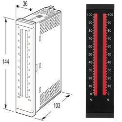
EXTERNAL DIMENSIONS & TERMINAL ASSIGNMENTS unit: mm (inch)
Mã số : 48NV BARGRAPH INDICATOR
36 x 144 mm
Red, Amber, Green, Blue LED
Vertical or horizontal mounting
100-264 Vac or 24 Vdc powered
IP 65 front panel cover
48NV BARGRAPH INDICATOR
Email : sales@m-system.com.vn
M-SYSTEM VIETNAM OFFICE
Hanoi Ofice: No 9, 651/82/3 Minh Khai street- Hai Ba Trung Dist. Hanoi Vietnam
Web: M-system.com.vn
Mã số : 48SV2 BARGRAPH INDICATOR
18 x 72 mm
Red, Amber, Green, Blue LED
Vertical or horizontal mounting
24 Vdc powered
51-segment LED (0 - 100% display: 51)
48SV2 BARGRAPH INDICATOR
Email : sales@m-system.com.vn
M-SYSTEM VIETNAM OFFICE
Hanoi Ofice: No 9, 651/82/3 Minh Khai street- Hai Ba Trung Dist. Hanoi Vietnam
Web: M-system.com.vn
Mã số : 48NAV 48NAVA 48NAVD BARGRAPH INDICATING ALARM
36 x 144 mm
Red, Amber, Green, Blue or Multicolor (red/orange/green) LED
Vertical or horizontal mounting
Dual or quad alarm
100-264 Vac or 24 Vdc powered
IP 65 front panel cover
48NAV 48NAVA 48NAVD BARGRAPH INDICATING ALARM
Email : sales@m-system.com.vn
M-SYSTEM VIETNAM OFFICE
Hanoi Ofice: No 9, 651/82/3 Minh Khai street- Hai Ba Trung Dist. Hanoi Vietnam
Web: M-system.com.vn
Mã số : 48NAT BARGRAPH INDICATING ALARM
36 x 144 mm
Red, Amber, Green, Blue or Multicolor (red/orange/green) LED
Vertical or horizontal mounting
Dual or quad alarm
100-264 Vac or 24 Vdc powered
IP 65 front panel cover
48NAT BARGRAPH INDICATING ALARM
Email : sales@m-system.com.vn
M-SYSTEM VIETNAM OFFICE
Hanoi Ofice: No 9, 651/82/3 Minh Khai street- Hai Ba Trung Dist. Hanoi Vietnam
Web: M-system.com.vn
Mã số : 48NAR BARGRAPH INDICATING ALARM
36 x 144 mm
Red, Amber, Green, Blue or Multicolor (red/orange/green) LED
Vertical or horizontal mounting
Dual or quad alarm
100-264 Vac or 24 Vdc powered
IP 65 front panel cover
48NAR BARGRAPH INDICATING ALARM
Email : sales@m-system.com.vn
M-SYSTEM VIETNAM OFFICE
Hanoi Ofice: No 9, 651/82/3 Minh Khai street- Hai Ba Trung Dist. Hanoi Vietnam
Web: M-system.com.vn
Mã số : 48NAM BARGRAPH INDICATING ALARM
Potentiometer input
48NAM BARGRAPH INDICATING ALARM
Email : sales@m-system.com.vn
M-SYSTEM VIETNAM OFFICE
Hanoi Ofice: No 9, 651/82/3 Minh Khai street- Hai Ba Trung Dist. Hanoi Vietnam
Web: M-system.com.vn
Mã số : 48NDV 48NDVA 48NDVD BARGRAPH INDICATING ALARM
36 x 144 mm
Red, Amber, Green, Blue or Multicolor (red/orange/green)LED
Dual or quad alarm
100-264 Vac or 24 Vdc powered
IP 65 front panel cover
48NDV 48NDVA 48NDVD BARGRAPH INDICATING ALARM
Email : sales@m-system.com.vn
M-SYSTEM VIETNAM OFFICE
Hanoi Ofice: No 9, 651/82/3 Minh Khai street- Hai Ba Trung Dist. Hanoi Vietnam
Web: M-system.com.vn
Mã số : 48NDT BARGRAPH INDICATING ALARM
Thermocouple input
48NDT BARGRAPH INDICATING ALARM
Email : sales@m-system.com.vn
M-SYSTEM VIETNAM OFFICE
Hanoi Ofice: No 9, 651/82/3 Minh Khai street- Hai Ba Trung Dist. Hanoi Vietnam
Web: M-system.com.vn
48NDR BARGRAPH INDICATING ALARM
Email : sales@m-system.com.vn
M-SYSTEM VIETNAM OFFICE
Hanoi Ofice: No 9, 651/82/3 Minh Khai street- Hai Ba Trung Dist. Hanoi Vietnam
Web: M-system.com.vn
Mã số : 48NDM BARGRAPH INDICATING ALARM
Potentiometer input
48NDM BARGRAPH INDICATING ALARM
Email : sales@m-system.com.vn
M-SYSTEM VIETNAM OFFICE
Hanoi Ofice: No 9, 651/82/3 Minh Khai street- Hai Ba Trung Dist. Hanoi Vietnam
Web: M-system.com.vn
4½ digit strain gauge input digital panel meter
• 1/8 DIN size
• Moving average function to suppress the display flickering
• Scaling, tare adjustment, low-end cutout
• Max. and Min. value display
• Safety terminal cover tethered to the device with a strap
• IP66 front panel
• Separable terminal block
Giá:
Call
Quảng cáo
THỐNG KÊ
Lượt truy cập:
334429
Đang online:
24
ĐỐI TÁC
CÔNG TY CỔ PHẦN KỸ THUẬT VÀ THƯƠNG MẠI THIẾT BỊ CÔNG NGHIỆP NTD
Địa chỉ: Số 28, ngõ 36 Cổ Linh, tổ 7, P. Long Biên, Q. Long Biên, TP. Hà Nội