·Some details are not shown. Please refer to specification sheets for all information.
PSN1
Final Control Elements
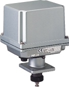
SERVO-TOP II ELECTRONIC ACTUATOR (linear type; max. thrust 3000 N)
Functions & Features • Control valve actuator drive • Lightweight, compact design • High reliability without electrical contacts • Friendly user interface • High resolution stepping motor • Failsafe (safety shutdown) function optional
MODEL: PSN1–4[1][2]–[3][4][5]
ORDERING INFORMATION • Code number: PSN1-4[1][2]-[3][4][5] Specify a code from below for each of [1] through [5]. (e.g. PSN1-421-AK3/E) • Use Ordering Information Sheet (No. ESU-4857). Default setting (table below) will be used if not otherwise specified.
STROKE 4: 0 to 40 mm (0” to 1.57”)
[1] SEALING SPRING 1: 1500 N use 2: 3000 N use
[2] OUTPUT STEM TYPE 1: M14 male screw, pitch 1.5 2: Stem button
[3] INPUT Current A: 4 – 20 mA DC (Input resistance 250 Ω) Voltage 6: 1 – 5 V DC (Input resistance 1 MΩ min.)
[4] POWER INPUT AC Power K3: 100 – 120 V AC (Operational voltage range 90 – 132 V, 47 – 66 Hz) (CE not available) L3: 200 – 240 V AC (Operational voltage range 180 – 264 V, 47 – 66 Hz) DC Power R: 24 V DC (Operational voltage range 24 V ±10 %, ripple 10 %p-p max.)
[5] OPTIONS Failsafe Function (emergency use) blank: Without /E: With Wiring conduits blank: G 1/2" /C: G 3/4" (Not available for option /E)
RELATED PRODUCTS • Manual operation handle (model: HPSN) • Programming Unit (model: PU-2x) • Backup battery (model: PSN-BAT)
GENERAL SPECIFICATIONS Degree of protection: IP66 Action: Direct or reverse; field selectable with DIP switches In “reverse” action, the output stem is retracted with an input signal increase. Operation at abnormally low input: Extend, retract or stop; field selectable with DIP switches Detectable input drop level: 0.37 ±0.1 V DC; converted into voltage Wiring conduits: G 1/2 female thread (two) (G 3/4 female thread (two) for /C) Terminal block: 7.62 mm pitch; M3 screw terminals (torque 0.5 N·m) Screw terminal: Nickel-plated brass Housing material: Diecast aluminum Coating: Silver color Drive: Stepping motor Insulation class: E Power control element: Power MOS-FET Position detection: Brushless angle sensor Full-open and full-closed positions: Any point within the full stroke; minimum stroke 8 % of the full stroke; field adjustable with control buttons Full-open/-closed (extended) signal adj.: 0 – 25 % Full-open/-closed (retracted) signal adj.: 75 – 100 % Extended side limiter adjustment: -5 – +25 % Retracted side limiter adjustment: 75 – 105 % Deadband adjustment: 0.1 – 5.0 % Restart limiting timer adjustment: 0 – 30 sec. Opening/closing speed adjustment: 0.30 – 5.65 mm/s Failsafe target position adjustment: 0 – 100 % (with failsafe function only) Isolation AC powered: Signal to power to sequential signal to battery status (with failsafe function only) to metallic housing DC powered: Signal or power to sequential signal to battery status (with failsafe function only) to metallic housing Fuse AC powered: 3 A (replaceable) DC powered: 4 A (replaceable) Protective functions: Error detection, abnormal temperature increase protection, motor preheat Power indicator: Green LED turns on with power supplied. Input indicator: Green LED turns on with normal input Alarm indicator: Red LED turns on in error; blinks in 1-sec. intervals when abnormal temperature increase is detected. Manual operation: Available Adjustments: Programming Unit (model: PU-2x); Full-open/full-closed positions, extended/retracted side limiters, full-open/full-closed signals, split range, opening/closing speed, deadband, restart limiting timer, failsafe opening/closing speed (with failsafe function only), failsafe target position (with failsafe function only) ■ Battery (failsafe function option) Battery chemistry: NiCad Battery ambient temperature Charge: 0 to 55°C (32 to 131°F) Storage: -20 to +55°C (-4 to +131°F), short term -20 to +45°C (-4 to +113°F), long term Battery life: Rechargeable up to 500 times; or 3 years, whichever is shorter, depending upon conditions of use Drive capacity: Once Charge method: Trickle charge after full rapid charge Charge time: 180 minutes (completely discharged) Battery status indicator LED: Turns on with full charge; turns off with the power removed. Charge indicator LED: Turns on during rapid charge
INPUT SPECIFICATIONS ■ DC Current: Input resistor incorporated • Forced Operation: External contact signal input terminals provided for compulsory retracting or extending operation Rating: 5 V DC @ 2.5 mA Detection levels: ≤ 500 Ω, ≤ 1 V for ON; ≥ 10 kΩ, ≥ 4 V for OFF ■ Split Range: Specify split range type and split point. Split range type: LO or HI Split point: 30 – 70 %
OUTPUT SPECIFICATIONS ■ Position Signal: 4 – 20 mA DC Load resistance: ≤ 300 Ω • Sequential Control Signal: "Full-open", "full-closed" and "alarm" Open collector: 30 V DC @ 100 mA max. Saturation voltage: 1 V DC ■ Failsafe Function (optional) Battery status output: Outputs a signal in synchronization with the battery status indicator; ON with full charge and OFF with the power removed. Open collector: 30 V DC @ 100 mA Saturation voltage: 1 V DC
INSTALLATION Power consumption •AC: Approx. 240 VA •DC: Approx. 3 A Operating temperature: -25 to +55°C (-13 to +131°F) Battery rechargeable within 0 to 55°C (32 to 131°F) with faisafe function. Operating humidity: 30 to 85 %RH (non-condensing) Vibration: ≤ 2 G (19.6 m/s2) Mounting position: Upside-down mounting prohibited Weight: 5.9 kg (13.0 lb) 7.2 kg (15.9 lb) with failsafe function
PERFORMANCE Resolution: 0.04 mm Insulation resistance AC powered: ≥ 100 MΩ with 500 V DC (signal to power to sequential signal to battery status (with failsafe function only) to metallic housing) DC powered: ≥ 100 MΩ with 500 V DC (signal or power to sequential signal to battery status (with failsafe function only) to metallic housing) Dielectric strength AC powered: 2000 V AC @ 1 minute (signal or metallic housing to power to battery status (with failsafe function only) to sequential signal) 500 V AC @ 1 minute (signal to metallic housing) DC powered: 2000 V AC @ 1 minute (signal or power or metallic housing to battery status (with failsafe function only) to sequential signal) 500 V AC @ 1 minute (signal or power to metallic housing)
STANDARDS & APPROVALS EU conformity: EMC Directive EMI EN 61000-6-4 EMS EN 61000-6-2 Low Voltage Directive EN 61010-1 Installation Category II Pollution Degree 2 Signal or metallic housing or seq. signals or battery status (with failsafe function only) to power: Reinforced insulation (300 V) RoHS Directive EN 50581
TERMINOLOGY • Error Detection - When the position signal is deviated from the input signal but the output stem is stuck due to overload or certain malfunction, the PSN repeats starting the motor at the maximum torque for several items. If the stem is still stuck after that, the PSN outputs an alarm signal (LED turned ON) and stops power supply to the motor. - In order to reset the PSN, apply several times 0 % and 100 % input signals in turn, or turn off and on the power supply. • Abnormal Temperature Increase Protection When the incorporated temperature sensor detects an abnormal temperature increase in the motor, the alarm LED blinks (repeating 0.5-sec. ON – 0.5-sec. OFF) and the power supply to the motor is stopped until the temperature decreases to an acceptable level. This electronic actuator is designed to resume automatically power supply to the motor. It takes longer to resume normal operation when ambient temperature is higher. • Restart Limiting Timer This unit is equipped with a timer protecting the motor from overheating. The timer prevents the motor from restarting for a certain interval once the motor has been stopped within deadband. When the high temperature protection is activated in a high temperature ambient, adjust the timer to a longer interval. • Motor Preheat Function When this unit detects a temperature lower than 0°C or 32°F (approximate) on the surface of its motor, this unit supplies current to the motor in order to warm up and maintain its surface temperature at 5°C or 41°F (approximate). Maintain the power supply ON when this unit is used in the ambient temperature below 0°C or 32°F. • Sealing Spring The PSN is incorporated with springs to maintain sealing pressure when the valve is fully closed. Choose an appropriate sealing pressure. These springs provide the same pressure at both fully closed and fully open positions. Do not apply a greater pressure to the spring than specified.