MSP4 Final Control Elements
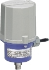
MINI-TOP ELECTRONIC ACTUATOR
(linear type)
Functions & Features
• Small-size control valve actuator
• 1/1000 high resolution
• Seal-spring incorporated for pressing direction
• Easy adjustment: electronic limiter at the valve open & closed positions
• Overload protection
• Various power inputs
• Manual operation function option available
Typical Applications
• Actuator for automatic control valve in pilotplants
• Air-conditioning in buildings or plants
• Micro-flow control for pharmaceutical injection
• For small-size control valves
MODEL: MSP4–[1][2][3][4][5]–[6][7][8][9]
ORDERING INFORMATION
• Code number: MSP4-[1][2][3][4][5]-[6][7][8][9]
Specify a code from below for each [1] through [9].
(e.g. MSP4-271LT-ACR/S/Q)
• Special input range (for codes Z and 0)
• Specify the specification for option code /Q
(e.g. /SET)
[1] STROKE
1: 5 to 10 mm (.20” to .39”)
2: 8 to 15 mm (.31” to .59”)
[2] OPERATION TIME, THRUST
3: 5 sec. / 10 mm, 150 N
4: 9 sec. / 10 mm, 300 N
7: 18 sec. / 10 mm, 700 N
[3] OUTPUT STEM TYPE
6: M6 female thread, 0.75 pitch
8: M8 female thread, 1.0 pitch
1: M10 female thread, 1.25 pitch
D: M6 female thread, 1.0 pitch
E: M8 female thread, 1.25 pitch
F: M10 female thread, 1.5 pitch
[4] SEQUENTIAL CONTROL SIGNALS
L: Full-open/-closed signal
F: Forced open/close signal
B: Full-open/-closed and forced open/close signals
(Select 'With Terminal Box.')
0: Without
[5] TERMINAL BOX
T: With
0: Without
[6] INPUT
Current
A: 4 – 20 mA DC (Input resistance 250 Ω)
Z: Specify current (See INPUT SPECIFICATIONS)
Voltage
6: 1 – 5 V DC (Input resistance approx. 1 MΩ)
0: Specify voltage (See INPUT SPECIFICATIONS)
[7] CE MARKING
C: With
0: Without
[8] POWER INPUT
AC Power
K3: 100 – 120 V AC
(Operational voltage range 90 – 132 V, 47 – 66 Hz)
(Not selectable for CE)
L3: 200 – 240 V AC
(Operational voltage range 180 – 264 V, 47 – 66 Hz)
(Not selectable for CE)
DC Power
R: 24 V DC
(Operational voltage range 24 V ±10 %, ripple 10 %p-p max.)
[9] OPTIONS (multiple selections)
Manual Operation Function
blank: Without
/S: With (Not available when DC power is selected.)
Other Options
blank: none
/Q: Option other than the above (specify the specification)
SPECIFICATIONS OF OPTION: Q
EX-FACTORY SETTING
/SET: Preset according to the Ordering Information Sheet
(No. ESU-4854)
GENERAL SPECIFICATIONS
Degree of protection: IP66
Action: Direct or reverse; field selectable with DIP switches (factory set to “reverse”)
(In “reverse” action with upright mount, the output stem goes up with an input signal increase.)
Operation at abnormally low input: go up, go down or stop; moving direction when upright mount, field selectable with DIP switches (factory set to “go down”)
Detectable input drop level: -16 ±2.5 %
Electrical connection
•Without terminal box
Wiring conduit: G 1/2 female; cable connector with 1 meter wire (0.5 mm2) provided
•Terminal box
Wiring conduit: G 1/2 female (two)
Terminal screws: M3 pillar terminal
(Sequential control signal suffix code B)
M3 chromated steel
(other terminal box types)
(torque 0.5 N·m)
Housing material: Diecast aluminum
Drive: Stepping motor
Position detection: Potentiometer
Deadband: 0.1 – 4.5 % adjustable (factory set to 1.5 %)
Restarting timer: 0 – 10 sec. adjustable
(factory set to 1.5 sec.)
Isolation: AC power to signal
Zero adjustment: 0 – 25 %
Span adjustment: 50 - 100 %
Protective functions: Overload protection
Power indicator: Green LED turns on with power supplied.
Input indicator: Green LED turns on with normal input
Status indicator LED: Red light blinks in 2 sec. intervals in normal operations; blinks in 0.5 sec. intervals when a foreign object is detected mechanically caught inside.
Manual operation: Optional
•MSP4-x3: 27 turns/mm
•MSP4-x4: 54 turns/mm
•MSP4-x7: 112 turns/mm
INPUT SPECIFICATIONS
■ DC Current: Input resistor incorporated (250 Ω)
■ DC Voltage: 1 – 5 V DC or specific range within 0 – 5 V DC, minimum span 1 V
(For a current input, convert the current to a voltage with 250 Ω)
Input resistance: Approx. 1 MΩ
■ Forced open/close signal: Dry contact inputs to command to go up and go down
Rating: 5 V DC @ 2.5 mA
(go up and go down when upright mount)
OUTPUT SPECIFICATIONS
■ Operation Time & Torque (at rated power voltage)
(Model: Operation Time: Thrust)
MSP4-x3: 5 sec. / 10 mm: 150 N (33.5 lbf)
MSP4-x4: 9 sec. / 10 mm: 300 N (67 lbf)
MSP4-x7: 18 sec. / 10 mm: 700 N (157 lbf)
■ DC Voltage: 1 – 5 V DC (not isolated)
With “direct” action, 5 – 1 V DC position output is provided proportionally to 4 – 20 mA DC (1 – 5 V DC) input.
Load resistance: ≥ 5 kΩ
■ Full-open / -closed signals: Limit switch contact
Rating: 125 V AC @ 0.75 A (cos ø = 1)
30 V DC @ 0.6 A (resistive load)
Mechanical life: 3 × 10⁷ cycles
Maximum operation frequency: 60 cycles/min.
INSTALLATION
Power consumption
•AC: Approx. 25 VA
•DC: Approx. 0.6 A
Operating temperature: -5 to +55°C (23 to 131°F)
Operating humidity: 30 to 85 %RH (non-condensing)
Vibration: 0.5 G (4.9 m/s2) max.
Mounting position: All directions
Do not mount the actuator with its output stem or cable connector on the upside if the actuator is to be exposed to dripping water.
Weight
•DC powered: 1.2 kg (2.65 lb)
•AC powered: 1.4 kg (3.09 lb)
Add 0.7 kg (1.54 lb) for the terminal box.
PERFORMANCE
Resolution: 1/1000 or 0.015 mm, whichever is greater, with 0.1 % deadband setting
Insulation resistance
•AC powered: ≥ 100 MΩ with 500 V DC
(signal or metallic housing to power)
≥ 100 MΩ with 100 V DC
(signal to metallic housing)
•DC powered: ≥ 100 MΩ with 100 V DC
(signal or power to metallic housing)
Dielectric strength
•AC powered: 1500 V AC @ 1 minute
(signal or metallic housing to power)
100 V AC @ 1 minute
(signal to metallic housing)
•DC powered: 100 V AC @ 1 minute
(signal or power to metallic housing)
STANDARDS & APPROVALS
EU conformity:
EMC Directive
EMI EN 61000-6-4
EMS EN 61000-6-2
Low Voltage Directive
EN 61010-1
Measurement Category II (Full-open/-closed signal)
Pollution Degree 2
Full-open/-closed signal to other, power or metallic
housing: Reinforced insulation (125 V)
RoHS Directive
EN 50581
TERMINOLOGY
• Overload (Lock) Protection
The Mini-Top Series is equipped with a protection circuit against overload caused by for example the valve catching an alien substance.
When an overload is detected, the Mini-Top stops supplying power to the motor and the status LED blinks in 0.5 sec. intervals.
The protection is reset automatically with applying opposite-direction input signal or turning the power off and restarting.
• Restarting Timer
The Mini-Top Series is equipped with a timer circuit which gives an interval period (0 – 10 seconds) between stop-restart actions to prevent the motor and other internal components from overheating.
It is recommended to set a long restarting time when the ambient temperature and/or the temperature of flow material is high.
• Electronic Limiter
This model is equipped with electronic limiters in order to prevent mechanical locks when the input goes below 0 % or above 100 %.
Limiters are set at approx. -1.5 % for the full-closed side, approx. 101.5 % for the full-open side.
• Seal-Spring
The Mini-Top Series incorporates a seal-spring to maintain the sealing pressure when the valve is fully closed. The standard spring has 0.5 – 1 mm (.02” – .04”) flexibility to facilitate the full-closed adjustment.
TERMINAL CONNECTIONS
EXTERNAL DIMENSIONS unit: mm (inch)
SCHEMATIC CIRCUITRY
M-System Vietnam Email: sales@m-system.com.vn
|