Functions & Features • Measures simultaneously several variables of a heavy-current power system: current, voltage, active, reactive, and apparent power, active and reactive energy, power factor, frequency, etc. • All measured values, counter values, setting data are stored in the non-volatile memory at the power off. • Conversion factors, system configuration, interval times are programmable. • Open collector output for alarm or energy count. Typical Applications • Multi-functional power measurement in electric device or in switching boards.
MODEL: L53U-1[1][2][3]-[4][5]
ORDERING INFORMATION • Code number: L53U-1[1][2][3]-[4][5] Specify a code from below for each [1] through [5]. (e.g. L53U-1211-AD4/H/A/Q) • Specify the specification for option code /Q (e.g. /C01/SET)
CONFIGURATION 1: Single-phase / 2-wire and 3-wire, 3-phase / 3-wire and 4-wire
[1] INPUT 1: 480 V / 1 A AC 2: 480 V / 5 A AC
[2] DISCRETE INPUT 0: None ( ‘External Interface’ codes 1, 4 and 5 Not selectable.) 1: 24 V DC (‘External Interface’ codes 2, 3, 6 and 7 Not selectable.) 2: 110 V DC (‘External Interface’ codes 2, 3, 6 and 7 Not selectable.)
[3] EXTERNAL INTERFACE 1: Modbus, Do × 1, Di × 1 2: 4 – 20 mA DC × 4 3: 1 – 5 V DC × 4 4: 4 – 20 mA DC × 2, Do × 1, Di × 1 5: 1 – 5 V DC × 2, Do × 1, Di × 1 6: 4 – 20 mA DC × 2, Do × 2 7: 1 – 5 V DC × 2, Do × 2
[4] AUXILIARY POWER SUPPLY AD4: universal 100 – 240 V AC (Operational range 85 – 264 V, 47 – 66 Hz) / 110 – 240 V DC (Operational range 99 – 264 V, ripple 10 %p-p max) R: DC Power 24 V DC (Operational range 19 – 29 V, ripple 10 %p-p max) (‘External interface’ codes 1, 4, 5, 6 and 7 Not selectable.)
[5] OPTIONS (multiple selections) Performance blank: Standard /H: High accuracy (voltage/current: ±0.2 %, energy: ±0.5 %) Configurator Software Switch /A: Without switch (must specify) Other Options blank: none /Q: Option other than the above (specify the specification)
SPECIFICATIONS OF OPTION: Q (multiple selections) COATING (For the detail, refer to M-System's web site.) /C01: Silicone coating /C02: Polyurethane coating /C03: Rubber coating EX-FACTORY SETTING /SET: Preset according to the Ordering Information Sheet (No. ESU-1958)
RELATED PRODUCTS • PC configurator software (model: PMCFG) • PC Recorder Light software for the 53U (model: MSR128LUx) Downloadable at M-System’s web site. A dedicated cable is required to connect the module to the PC. Please refer to the internet software download site or the users manual for the PC configurator for applicable cable types.
GENERAL SPECIFICATIONS Connection Voltage input: Connector type terminal block (applicable wire size: ≤ 2.5 dia, 0.5 – 3.5 mm2,stripped length 7 - 8 mm) Current input: Screw terminal block (applicable wire size: ≤ 2.4 dia, 0.5 – 3.5 mm2,stripped length 13 - 15 mm) Discrete input, discrete output, analog output, Modbus, auxiliary power supply: Connector type terminal block (applicable wire size: ≤ 2.4 dia, 0.5 – 2.5 mm2,stripped length 7 - 8 mm) Configuration: Single phase/2-wire and 3-wire, 3-phase/3-wire balanced/unbalanced load, 3-phase/4-wire balanced/unbalanced load Housing material: Flame-resistant resin (gray) Isolation: Voltage input to current input to discrete input to discrete output to Modbus or configurator jack or analog output to auxiliary power ■Measured variables Voltage: 1 – N, 2 – N, 3 – N, 1 – 2, 2 – 3, 3 – 1 Current: 1, 2, 3, N Active / reactive / apparent power: 1, 2, 3, Σ Power factor: 1, 2, 3, Σ Frequency Voltage phase angle: 1 – 2, 2 – 3, 3 – 1 Active energy: Incoming / outgoing / high tariff (peak) / low tariff (off-peak) Reactive energy:Incoming / outgoing / lag / lead / high tariff (peak) / low tariff (off-peak) Apparent energy Active / reactive / apparent average power (demand) Average current: 1, 2, 3,N Harmonic contents: Σ, 2nd to 31st Count time: High tariff / low tariff Max. and min. values Demand history: 1 to 4
INPUT SPECIFICATIONS Frequency: 50 / 60 Hz (45 – 65 Hz) • Voltage Input Rated voltage Line-to-line (delta voltage): 480 V Line-neutral (phase voltage): 277 V (single phase / 2-wire and 3-wire) Consumption VA: ≤ ULN2 / 300 kΩ / phase Overload capacity: 200 % of rating for 10 sec., 120 % continuous Selectable primary voltage range: 50 – 400 000 V • Current Input Rated current: 1 A or 5 A Consumption VA: ≤ I2 · 0.01 Ω / phase Overload capacity: 4000 % of rating for 1 sec., 2000 % for 4 sec., 120 % continuous Selectable primary current range: 1 – 20 000 A Selectable primary power range: ≤ 2 G VA Operational range Voltage, current, apparent power: ≤ 120 % of the rating Active / reactive power: -120 to +120 % of the rating Frequency: 45 – 65 Hz Power factor: -1 to +1 ■ Discrete Input: 24 V DC or 110 V DC (input resistance 6 kΩ) Detecting voltage: External 24 V DC ±10 % or 110 V DC ±10 % ON current: ≥ 1 mA (≤ 24 kΩ @ 24 V, ≤ 110 kΩ @110 V) OFF current: ≤ 0.1 mA (≥ 240 kΩ @ 24 V, ≥ 1.1 MΩ @ 110 V) Detecting time: 10 – 1000 msec. The status can be monitored on the Modbus; usable to reset energy count or to update average (demand) value.
OUTPUT SPECIFICATIONS ■ Modbus Communication: Half-duplex, asynchronous, no procedure Interface: Conforms to TIA/EIA-485-A Max. transmission distance: 500 meters Baud rate: 1.2 – 38.4 kbps Max. number of nodes: 31 (except the master) Protocol: Modbus RTU Node address: 1 – 247 (factory default setting: 1) Parity: none, even or odd (factory default setting: odd) Stop bit: 1 or 2 (factory default setting: 1) Media: Shielded twisted-pair cable (CPEV-S 0.9 dia.) ■ DC Current: 4 – 20 mA DC Load resistance: ≤ 270 Ω Measurands converted into analog output: Voltage, Current, Active / reactive / apparent power, Power factor, Frequency, Harmonic contents ■ DC Voltage: 1 – 5 V DC Load resistance: ≥ 5000 Ω Measurands converted into analog output: Voltage, Current, Active / reactive / apparent power, Power factor, Frequency, Harmonic contents ■ Open Collector Programmable for either alarm or energy count. Max. rated load: 130 V DC @50 mA Continuous rated load: 130 V DC @30 mA Saturation voltage: 1.5 V DC Measurands applicable to alarm: Voltage, current, average current (demand), neutral current, frequency, power, average power (demand) (ON delay, deadband and other parameters are selectable) Measurands applicable to count: Energy; Pulse rate selectable within 0.1 – 10 000.0 kWh/p, kvarh/p, kVAh/p
INSTALLATION Power consumption •AC: < 10 VA •DC: < 3 W Operating temperature: -10 to +55°C (14 to 131°F) Operating humidity: 30 to 90 %RH (non-condensing) Mounting: DIN rail Weight: 320 g (0.71 lb)
PERFORMANCE Accuracy (at 23°C ±10°C or 73.4°F ±18°F, 45 – 65 Hz) Voltage: ±0.3 % (±0.2 % for Option /H)*1 Current: ±0.3 % (±0.2 % for Option /H)*1 Power: ±0.5 %*1 Power factor: ±0.5 % Frequency: ±0.1 %*1 Energy: ±1 % (±0.5 % for Option /H*2) Harmonic contents: ±1 %*1 Analog output: Accuracy of assigned measurand or ±0.2 %, whichever is greater. *1. Percentage of the spans: 480 V for voltage; 1 A or 5 A for current; and 4155 W (5 A) or 831 W (1 A) for active power The described accuracy levels are ensured at the input 1 % or more for phase 2 current with 3-phase/3-wire unbalanced load, for neutral current with 3-phase/4-wire unbalanced load, and neutral current with 1-phase/3-wire. *2. Accuracy level: Active energy class 0.5S according to IEC 62053-22 (Reactive energy class 2 according to IEC 62053-23) Sampling rate: 64 samples per cycle Data update period: Harmonic contents and frequency: ≤ 1.1 sec. Other: ≤ 600 msec. Response time: ≤ 2 sec. (0 – 99 %), ≤ 3 sec. for frequency and harmonic contents Insulation resistance: ≥ 100 MΩ with 500 V DC Dielectricstrength: 4000 V AC @1 minute (voltage input or current input or discrete input or discrete output or Modbus or configurator jack or analog output to auxiliary power) 2500 V AC @1 minute (voltage input to current input to discrete input to discrete output to Modbus or configurator jack or analog output)
STANDARDS & APPROVALS EU conformity: EMC Directive EMI EN 61000-6-4 EMS EN 61000-6-2 Low Voltage Directive EN 61010-1 Measurement Category III (input) (Measurement Category II if the auxiliary power supply code is R) Measurement Category II (output) Installation Category II (auxiliary power) Pollution Degree 2 Input to auxiliary power: Reinforced insulation (550 V) Output to auxiliary power: Reinforced insulation (300 V) Input to output: Basic insulation (550 V) RoHS Directive EN 50581
Mã số : CLSE CLAMP-ON CURRENT SENSOR
Easy-to-install, spring-loaded, clamp-on type current sensor
Over-voltage clamp element for safety in open circuit
Wide frequency band
Screw terminal connection
CLSE CLAMP-ON CURRENT SENSOR
M-System Việt Nam
Email: Sales@m-system.com.vn
Mã số : CLSC - CLAMP-ON CURRENT SENSOR
Easy-to-install, clamp-on type current sensor
Over-voltage clamp element for safety in open circuit
1A Output
Wide frequency band
Screw terminal connection
CLSC - CLAMP-ON CURRENT SENSOR
M-System Việt Nam
Email: Sales@m-system.com.vn
Mã số : CTS2 - HIGH AC CURRENT TRANSMITTER
Detecting high current at the flexible current probe and
providing a porportional low-ripple standard signal
appropriate for computer use
Wide frequency band can be accepted
Clipped around a conductor without disconnecting the conductor
Rogowski coil type
Isolation up to 2000 V AC
High-density mounting
CTS2 - HIGH AC CURRENT TRANSMITTER
M-System Việt Nam
Email: Sales@m-system.com.vn
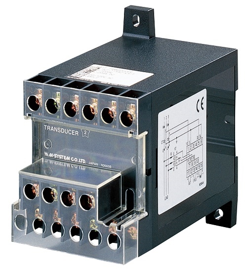
Mã số : L53U MULTI POWER TRANSDUCER
Single type module is usable for all of single-phase/2-wire and 3-wire, three-phase/3-wire and 4-wire systems.
All measured variables can be transmitted to the host PC via RS-485/Modbus RTU.
Energy count pulse or limit alarm output selectable
Up to 4 optional analog outputs
Remote and local programming using the PC Configurator Software
Input range up to 480 Vac, 1 A or 5 A
DIN rail mounted
L53U MULTI POWER TRANSDUCER
M-System Việt Nam
Email: Sales@m-system.com.vn
Mã số : 54UL MULTI POWER MONITOR
110 x 110 mm panel size
Robust screw terminal connection
Four digital displays
60-segment bargraph
Single-phase/2-wire and 3-wire, three-phase/3-wire and 4-wire systems
All measured variables can be transmitted to the host PC via RS-485/Modbus RTU or CC-Link,LONWORKS
Energy count pulse or limit alarm output selectable
Up to 4 optional analog outputs
Programming lock to prevent unwanted configuration changes
Input range up to 480 Vac, 1 A or 5 A
Modbus:54U CC-Link:54UC LONWORKS:54UL
54UL MULTI POWER MONITOR
M-System Việt Nam
Email: Sales@m-system.com.vn
Mã số : 54UC MULTI POWER MONITOR
110 x 110 mm panel size
Robust screw terminal connection
Four digital displays
60-segment bargraph
Single-phase/2-wire and 3-wire, three-phase/3-wire and 4-wire systems
All measured variables can be transmitted to the host PC via RS-485/Modbus RTU or CC-Link,LONWORKS
Energy count pulse or limit alarm output selectable
Up to 4 optional analog outputs
Programming lock to prevent unwanted configuration changes
Input range up to 480 Vac, 1 A or 5 A
Modbus:54U CC-Link:54UC LONWORKS:54UL
54UC MULTI POWER MONITOR
M-System Việt Nam
Email: Sales@m-system.com.vn
• Converts alternating current from a current transformer
into a standard process signal
• Minimum ripple
• Isolation up to 2000 V AC
• High-density mounting
• Conforms to IEC 60688