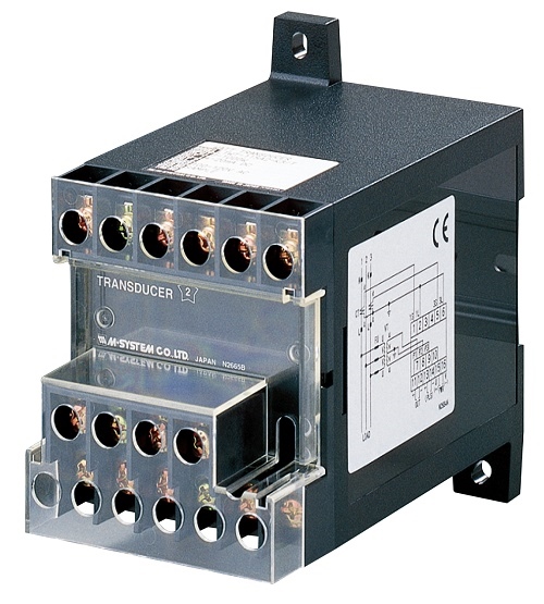
LTHZN - FREQUENCY TRANSDUCER
(self-powered)
Functions & Features
• Provides a DC output signal in proportion to the deviation (±5 Hz) from the center frequency (50 Hz or 60 Hz)
• DC output containing little ripple is ideal for computer input
• No auxiliary power supply required
• Isolation up to 2000 V AC
• High-density mounting
• Conforms to IEC 60688
Typical Applications
• Centralized monitoring and control of power management system in manufacturing facility or building
• Measuring frequency for UPS
MODEL: LTHZN–[1][2][3][4]
ORDERING INFORMATION
• Code number: LTHZN–[1][2][3][4]
Specify a code from below for each of [1] through [4].
(e.g. LTHZN-11A/T/Q)
• Special output range (For codes Z & 0)
• Specify the specification for option code /Q
(e.g. /C01)
[1] FREQUENCY
1: 45 – 55 Hz
2: 55 – 65 Hz
3: 45 – 65 Hz
[2] VT INPUT
1: 110 V AC
2: 220 V AC
[3] OUTPUT
Current
A: 4 – 20 mA DC (Load resistance 500 Ω max.)
D: 0 – 20 mA DC(Load resistance 500 Ω max.)
F: 0 – 10 mA DC (Load resistance 1000 Ω max.)
G: 0 – 1 mA DC (Load resistance 10 kΩ max.)
J: 0 – 5 mA DC (Load resistance 2000 Ω max.)
Z: Specify current (See OUTPUT SPECIFICATIONS)
Voltage
1: 0 – 10 mV DC (Load resistance 10 kΩ min.)
2: 0 – 100 mV DC (Load resistance 100 kΩ min.)
3: 0 – 1 V DC (Load resistance 1000 Ω min.)
4: 0 – 10 V DC (Load resistance 10 kΩ min.)
5: 0 – 5 V DC (Load resistance 5000 Ω min.)
6: 1 – 5 V DC (Load resistance 5000 Ω min.)
0: Specify voltage (See OUTPUT SPECIFICATIONS)
[4] OPTIONS (multiple selections)
Terminal Cover
blank: Without
/T: With
Other Options
blank: none
/Q: Option other than the above (specify the specification)
SPECIFICATIONS OF OPTION: Q
COATING (For the detail, refer to M-System's web site.)
/C01: Silicone coating
/C02: Polyurethane coating
/C03: Rubber coating
GENERAL SPECIFICATIONS
Connection: M4 screw terminals (torque 1.2 N·m)
Screw terminal: Chrome-plated steel
Housing material: Flame-resistant resin (black)
Isolation: Input to output
Computation: One-shot
Overrange output: Approx. -10 to +120 % at 1 – 5 V
Zero adjustment: -5 to +5 % (front)
Span adjustment: 95 to 105 % (front)
INPUT SPECIFICATIONS
Operational range: 85 – 110 % of rating
Overload capacity: 150 % of rating for 10 sec., 110 % continuous
Input burden: 3 VA
OUTPUT SPECIFICATIONS
■ DC Current: 0 – 20 mA DC
Minimum span: 1 mA
Offset: Max. 1.5 times span
Load resistance: Output drive 10 V max.
■ DC Voltage: 0 – 12 V DC
Minimum span: 5 mV
Offset: Max. 1.5 times span
Load resistance: Output drive 1 mA max.; at ≥ 0.5 V
INSTALLATION
Operating temperature: -10 to +55°C (14 to 131°F)
Operating humidity: 30 to 85 %RH (non-condensing)
Mounting: Surface or DIN rail
Weight: 400 g (0.88 lb)
PERFORMANCE in percentage of span
Accuracy: ±0.2 % (at 23°C ±10°C or 73.4°F ±18°F, 45 – 65 Hz)
Magnetic field (ext. origin) effect: ±0.2 % (400 A/m)
Response time: ≤ 1 sec. (0 – 100 % ±1 %)
Ripple: 0.5 %p-p max.
Insulation resistance: ≥ 100 MΩ with 500 V DC
Dielectric strength: 2000 V AC @1 minute
(input to output to ground)
Impulse withstand voltage: 1.2 / 50 μsec., ±5 kV
(input to output or ground)
STANDARDS & APPROVALS
EU conformity:
EMC Directive
EMI EN 61000-6-4
EMS EN 61000-6-2
Low Voltage Directive
EN 61010-1
Measurement Category II (input)
Pollution Degree 2
Input to output: Reinforced insulation (300 V)
RoHS Directive
EN 50581
CONNECTION DIAGRAM
EXTERNAL DIMENSIONS & TERMINAL ASSIGNMENTS unit: mm (inch)
M-System Việt Nam Email: Sales@m-system.com.vn
|