M2CEC AC CURRENT TRANSMITTER (clamp-on current sensor)
Functions & Features • Converts an alternating current into a standard process signal • Easy-to-install clamp-on type current sensor with no need of a current transformer • Clamp-on current sensor included • Wide input range from 10A up to 600A • Input frequency 50 / 60 / 400 Hz • Over-voltage clamp element for safety in open circuit • True RMS sensing • Universal power input • High-density mounting Typical Applications • Centralized monitoring and control of motors at a supervisory panel • Monitoring abnormal load current at motors to detect pump malfunctions
MODEL: M2CEC-[1][2][3]-[4][5]
ORDERING INFORMATION • Code number: M2CEC-[1][2][3]-[4][5] Specify a code from below for each [1] through [5]. (e.g. M2CEC-150A-M/Q) • Special output range (For codes Z & 0) • Specify the specification for option code /Q (e.g. /C01/S01)
[1] SENSOR 1: Leadwire type CLSA 2: Screw terminal type CLSB
[2] INPUT 10: 0 – 10 A AC 15: 0 – 15 A AC 20: 0 – 20 A AC 30: 0 – 30 A AC 40: 0 – 40 A AC 50: 0 – 50 A AC 60: 0 – 60 A AC 75: 0 – 75 A AC 100: 0 – 100 A AC 125: 0 – 125 A AC 150: 0 – 150 A AC 175: 0 – 175 A AC 200: 0 – 200 A AC 225: 0 – 225 A AC 250: 0 – 250 A AC 300: 0 – 300 A AC 350: 0 – 350 A AC 400: 0 – 400 A AC 500: 0 – 500 A AC 600: 0 – 600 A AC (Not selectable with the sensor type code 1 'Leadwire type CLSA')
[3] OUTPUT Current A: 4 – 20 mA DC (Load resistance 750 Ω max.) B: 2 – 10 mA DC (Load resistance 1500 Ω max.) C: 1 – 5 mA DC (Load resistance 3000 Ω max.) D: 0 – 20 mA DC (Load resistance 750 Ω max.) E: 0 – 16 mA DC (Load resistance 900 Ω max.) F: 0 – 10 mA DC (Load resistance 1500 Ω max.) G: 0 – 1 mA DC (Load resistance 15 kΩ max.) Z: Specify current (See OUTPUT SPECIFICATIONS) Voltage 1: 0 – 10 mV DC (Load resistance 10 kΩ min.) 2: 0 – 100 mV DC (Load resistance 100 kΩ min.) 3: 0 – 1 V DC (Load resistance 1000 Ω min.) 4: 0 – 10 V DC (Load resistance 10 kΩ min.) 5: 0 – 5 V DC (Load resistance 5000 Ω min.) 6: 1 – 5 V DC (Load resistance 5000 Ω min.) 4W: -10 – +10 V DC (Load resistance 10 kΩ min.) 5W: -5 – +5 V DC (Load resistance 5000 Ω min.) 0: Specify voltage (See OUTPUT SPECIFICATIONS)
[4] POWER INPUT AC Power M: 85 – 264 V AC (Operational voltage range 85 – 264 V, 47 – 66 Hz) DC Power R: 24 V DC (Operational voltage range 24 V ±10 %, ripple 10 %p-p max.) R2: 11 – 27 V DC (Operational voltage range 11 – 27 V, ripple 10 %p-p max.) P: 110 V DC (Operational voltage range 85 – 150 V, ripple 10 %p-p max.)
[5] OPTIONS Other Options blank: none /Q: Option other than the above (specify the specification)
SPECIFICATIONS OF OPTION: Q (multiple selections) COATING (For the detail, refer to M-System's web site.) /C01: Silicone coating /C02: Polyurethane coating /C03: Rubber coating TERMINAL SCREW MATERIAL /S01: Stainless steel
ACCESSORIES The clamp-on current sensor is included in the product package. ■ CLAMP-ON CURRENT SENSOR (leadwire type CLSA) • 0 – 10 A through 0 – 75 A Use Sensor model No.: CLSA-08 Sensor cable model No.: CLSA-08C-30 Applicable cable diameter: Max. 10.0 Sensor leadwire: AWG 22 Weight: 45 g (1.6 oz) • 0 – 100 A Use Sensor model No.: CLSA-12 Sensor cable model No.: CLSA-08C-30 Applicable cable diameter: Max. 16.0 Sensor leadwire: AWG 22 Weight: 70 g (2.5 oz) • 0 – 125 A through 0 – 300 A Use Sensor model No.: CLSA-30 Applicable cable diameter: Max. 24.0 Sensor leadwire: AWG 18, 200 mm Weight: 200 g (7.1 oz) • 0 – 350 A through 0 – 500 A Use Sensor model No.: CLSA-50 Applicable cable diameter: Max. 36.0 Sensor leadwire: AWG 18, 200 mm Weight: 300 g (10.6 oz) ■ CLAMP-ON CURRENT SENSOR (screw terminal type CLSB) Connection: M3 screw terminal (torque 0.5 N·m) Screw terminal: Nickel-plated steel Output wiring: Use AWG22 or thicker wires for the output. Twist the paired wires, extendable up to 30 meters. • 0 – 10 A through 0 – 50 A Use Sensor model No.: CLSB-05 Applicable cable diameter: Max. 10.0 Weight: 45 g (1.6 oz) • 0 – 60 A through 0 – 100 A Use Sensor model No.: CLSB-10 Applicable cable diameter: Max. 16.0 Weight: 80 g (2.8 oz) • 0 – 125 A through 0 – 200 A Use Sensor model No.: CLSB-20 Applicable cable diameter: Max. 24.0 Weight: 200 g (7.1 oz) • 0 – 225 A through 0 – 400 A Use Sensor model No.: CLSB-40 Applicable cable diameter: Max. 35.0 Weight: 300 g (10.6 oz) • 0 – 500 A through 0 – 600 A Use Sensor model No.: CLSB-60 Applicable cable diameter: Max. 35.0 Weight: 360 g (12.7 oz) Note 1: The output values may vary depending on the accuracy of engagement at the clamp connection. Note 2: The sensor is detachable up to 100 times (approx.). Note 3: The sensor’s mechanical construction may cause it to generate resonance sound. However, it does not affect the performance of the sensor.
GENERAL SPECIFICATIONS Construction: Plug-in Connection: M3 screw terminals (torque 0.8 N·m) Screw terminal: Chromated steel (standard) or stainless steel Housing material: Flame-resistant resin (black) Isolation: Sensor core to input to output to power Input waveform RMS sensing: Up to 15 % of 3rd harmonic content Overrange output: 0 to 120 % at 1 – 5 V Zero adjustment: -5 to +5 % (front) Span adjustment: 95 to 105 % (front)
INPUT SPECIFICATIONS Frequency: 50 / 60 / 400 Hz Overload capacity CLSA - 08: 120 A continuous CLSA - 12: 300 A continuous CLSA - 30: 360 A continuous CLSA - 50: 600 A continuous CLSB - 05: 100 A continuous CLSB - 10: 200 A continuous CLSB - 20: 300 A continuous CLSB - 40: 600 A continuous CLSB - 60: 720 A continuous Operational range: 0 – 120 % of rating Be sure that the input voltage is of 440 V or less.
OUTPUT SPECIFICATIONS ■ DC Current: 0 – 20 mA DC Minimum span: 1 mA Offset: Max. 1.5 times span Load resistance: Output drive 15 V max. ■ DC Voltage: -10 – +12 V DC Minimum span: 5 mV Offset: Max. 1.5 times span Load resistance: Output drive 1 mA max.; at ≥ 0.5 V
INSTALLATION Power Consumption •AC: Approx. 3 VA at 100 V Approx. 4 VA at 200 V Approx. 5 VA at 264 V •DC: Approx. 3 W Operating temperature: -5 to +55°C (23 to 131°F) Operating humidity: 30 to 90 %RH (non-condensing) Mounting: Surface or DIN rail Weight: 150 g (0.33 lb)
PERFORMANCE in percentage of span Accuracy: ±0.5 % (±1.0 % at 400 Hz) Temp. coefficient: ±0.05 %/°C (±0.03 %/°F) Response time: ≤ 0.7 sec. (0 – 90 %) Ripple: 0.5 %p-p max. (50/60 Hz) Line voltage effect: ±0.1 % over voltage range Insulation resistance: ≥ 100 MΩ with 500 V DC Dielectric strength: 2000 V AC @1 minute (input to output to power to ground) 1000 V AC @1 minute (sensor core to sensor output)
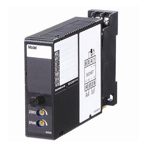
EXTERNAL DIMENSIONS & TERMINAL ASSIGNMENTS unit: mm (inch)
Mã số : W2CE CURRENT TRANSMITTER
0-110 V or 0-150 V
Independent current/voltage output ranges can be specified.
100-240 Vac or 24 Vdc powered
UL/cUL Class I, Div. 2 approval
W2CE CURRENT TRANSMITTER
M-System Việt Nam
Email: Sales@m-system.com.vn
Mã số : W2CA CURRENT TRANSMITTER
0-110 V or 0-150 V
Independent current/voltage output ranges can be specified.
100-240 Vac or 24 Vdc powered
UL/cUL Class I, Div. 2 approval
W2CA CURRENT TRANSMITTER
M-System Việt Nam
Email: Sales@m-system.com.vn
Mã số : M2FV SIGNAL TRANSMITTER
Free I/O range combinations among 4-20 mA, 0-20 mA, 0-10 V, 2-10 V,
0-5 V and 1-5 V
Response time is also selectable with DIP switch between 0.5 sec. and 30 msec.
85-264, 100-240 Vac or 11-27, 24, 110 Vdc powered
Ideal for quick-relief spare parts
M2FV SIGNAL TRANSMITTER
M-System Việt Nam
Email: Sales@m-system.com.vn
Mã số : W2DNY CURRENT LOOP SUPPLY
4-20 mA input
Supply output 24-28 V @22 mA
Independent current/voltage output ranges can be specified
100-240 Vac or 24 Vdc powered
Low-end cutout
W2DNY CURRENT LOOP SUPPLY
M-System Việt Nam
Email: Sales@m-system.com.vn
Mã số : M2AC AC TRANSMITTER
Specific input range within 0-250 V or 0-1 A
Min. 40 Hz, max. 1 kHz
100-240 Vac or 24 Vdc powered
UL/cUL Class I, Div. 2 approval
M2AC AC TRANSMITTER
M-System Việt Nam
Email: Sales@m-system.com.vn
Mã số : M60SWVS SIGNAL TRANSMITTER
Two isolated outputs
Spring clamp terminal connection for easy wiring
6-mm wide ultra-slim design
Input range field-selectable among 6 options
Output range field-selectable among 4 options
M60SWVS SIGNAL TRANSMITTER
M-System Việt Nam
Email: Sales@m-system.com.vn
Mã số : W5FV SIGNAL TRANSMITTER
Input range field-selectable among 11 options
Output range field-selectable among 7 options
Optional second output of independent range can be specified when ordering
85-264 Vac or 11-27, 24, 110 Vdc powered (CE for 24 Vdc type)
W5FV SIGNAL TRANSMITTER
M-System Việt Nam
Email: Sales@m-system.com.vn
Mã số : W2AC AC TRANSMITTER
Specific input range within 0-250 V or 0-1 A
Min. 40 Hz, max. 1 kHz
Independent current/voltage output ranges can be specified.
100-240 Vac or 24 Vdc powered
UL/cUL Class I, Div. 2 approval
W2AC AC TRANSMITTER
M-System Việt Nam
Email: Sales@m-system.com.vn
Mã số : M3LV SIGNAL TRANSMITTER
Input selectable within 0-20 mA and ±10 V
Output selectable within 0-20 mA and ±10 V
10-32 Vdc powered
DIP switch or PC configuration
M3LV SIGNAL TRANSMITTER
M-System Việt Nam
Email: Sales@m-system.com.vn
Mã số : M5MV SIGNAL TRANSMITTER
Specific input range within ±100 mV; current input with a resistor
85-264 Vac or 24 Vdc powered (CE for 24 Vdc type)
Fast response 25 msec. optional
M5MV SIGNAL TRANSMITTER
M-System Việt Nam
Email: Sales@m-system.com.vn
Mã số : M5DY CURRENT LOOP SUPPLY
4-20 mA input
Supply output 24-28 V @22 mA
Signal output 4-20 mA and other voltage or current range
100-240 Vac or 24 Vdc powered (CE for 24 Vdc type)
Economical model
M5DY CURRENT LOOP SUPPLY
M-System Việt Nam
Email: Sales@m-system.com.vn
Mã số : W5DY CURRENT LOOP SUPPLY
4-20 mA input
Supply output 24-28 V @22 mA
Signal output 4-20 mA and other voltage or current range
Independent output ranges selectable
100-240 Vac or 24 Vdc powered (CE for 24 Vdc type
W5DY CURRENT LOOP SUPPLY
M-System Việt Nam
Email: Sales@m-system.com.vn
Mã số : M2DNY CURRENT LOOP SUPPLY
4-20 mA input
Supply output 24-28 V @22 mA
Signal output 4-20 mA and other voltage or current range
100-240 Vac or 24 Vdc powered
Low-end cutout
M2DNY CURRENT LOOP SUPPLY
M-System Việt Nam
Email: Sales@m-system.com.vn
Mã số : W2TG TACHOGENERATOR TRANSMITTER
Specific input range within 0-250 V
Min. 15 Hz, max. 1 kHz
Independent current/voltage output ranges can be specified.
100-240 Vac or 24 Vdc powered
UL/cUL Class I, Div. 2 approval
W2TG TACHOGENERATOR TRANSMITTER
M-System Việt Nam
Email: Sales@m-system.com.vn
Mã số : M2TG TACHOGENERATOR TRANSMITTER
Specific input range within 0-250 V
Min. 15 Hz, max. 1 kHz
100-240 Vac or 24 Vdc powered
UL/cUL Class I, Div. 2 approval
M2TG TACHOGENERATOR TRANSMITTER
M-System Việt Nam
Email: Sales@m-system.com.vn
Powering a 4 – 20 mA DC current loop
• Applicable to smart transmitters
• Isolation between the input and output
• Fast response type available
• High-density mounting
• Power LED
Signal conditioners convert a field signal from various sensors into standard signal suitable for processing in PLC, DCS or PC-based systems. They are also used to boost a signal to increase load drive capability, to isolate a signal to stop ground loops.
More than 75000 combinations of process signal I/O, power input and mounting configuration are selectable. Additionally, M-System offers the broadest line of signal splitters available.
M2 / M2E Series Signal Conditioners are designed to accept a largest range of process signal inputs and provide a standard and non-standard DC output.
M2E Series are Compact Signal Conditioners with OEL display.