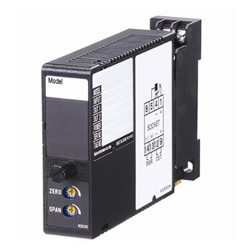
M2D2 CURRENT LOOP SUPPLY
(non-isolated, with indicator LED)
Functions & Features
• Powers a 4 – 20mA DC current loop
• Electrically isolating output signal from power input
• Shortcircuit protection
• Applicable to smart transmitters
Typical Applications
• Various 2-wire transmitters
MODEL: M2D2–24–[1][2]
ORDERING INFORMATION
• Code number: M2D2-24-[1][2]
Specify a code from below for each [1] and [2].
(e.g. M2D2-24-R/CE/Q)
• Specify the specification for option code /Q
(e.g. /C01/S01)
SUPPLY OUTPUT
24: 24 V DC
INPUT
Current
4 – 20 mA DC (Input resistance 250 Ω)
OUTPUT 1
Voltage
1 – 5 V DC (Load resistance 250 kΩ min.)
OUTPUT 2
Current
4 – 20 mA DC
[1] POWER INPUT
AC Power
M2: 100 – 240 V AC (Operational voltage range 85 – 264 V,
47 – 66 Hz)
(90 – 264 V for UL)
DC Power
R: 24 V DC
(Operational voltage range 24 V ±10 %, ripple 10 %p-p max.)
R2: 11 – 27 V DC
(Operational voltage range 11 – 27 V, ripple 10 %p-p max.)
(Select ‘/N’ for ‘Standards & Approvals’ code.)
P: 110 V DC
(Operational voltage range 85 – 150 V, ripple 10 %p-p max.)
(110 V ±10 % for UL)
[2] OPTIONS (multiple selections)
Standards & Approvals (must be specified)
/N: Without CE or UL
/CE: CE marking
/UL: UL approval, CE marking
Other Options
blank: none
/Q: Option other than the above (specify the specification)
SPECIFICATIONS OF OPTION: Q (multiple selections)
COATING (For the detail, refer to M-System's web site.)
/C01: Silicone coating
/C02: Polyurethane coating
/C03: Rubber coating (UL not available)
TERMINAL SCREW MATERIAL
/S01: Stainless steel (UL not available)
GENERAL SPECIFICATIONS
Construction: Plug-in
Connection: M3 screw terminals (torque 0.8 N·m)
Screw terminal: Chromated steel (standard) or stainless steel
Housing material: Flame-resistant resin (black)
Isolation: Input or output to power
Indicator LED: Red light turns on during operation.
SUPPLY OUTPUT
Output voltage: 24V DC with no load
Current rating: 30mA
∙Shortcircuit Protection
Current limited: Approx. 30 mA
Protected time duration: No limit
INPUT SPECIFICATIONS
■ DC Current: Input resistor incorporated
INSTALLATION
Power Consumption
•AC:
Approx. 3 VA at 100 V
Approx. 4 VA at 200 V
Approx. 5 VA at 264 V
•DC: Approx. 3 W
Operating temperature: -5 to +55°C (23 to 131°F)
Operating humidity: 30 to 90 %RH (non-condensing)
Mounting: Surface or DIN rail
Weight: 150 g (0.33 lb)
PERFORMANCE in percentage of span
Accuracy: ±0.1 % (accuracy of the receiving resistor)
Temp. coefficient: ±0.003 %/°C (±0.002 %/°F) (temp. coefficient of the receiving resistor)
Line voltage effect to supply output: ±3 % over voltage range
Insulation resistance: ≥ 100 MΩ with 500 V DC
Dielectric strength: 2000 V AC @1 minute (input or output to power to ground)
STANDARDS & APPROVALS
EU conformity:
EMC Directive
EMI EN 61000-6-4
EMS EN 61000-6-2
Low Voltage Directive
EN 61010-1
Installation Category II
Pollution Degree 2
Input or output to power: Reinforced insulation (300 V)
RoHS Directive
EN 50581
Approval:
UL/C-UL nonincendive Class I, Division 2,
Groups A, B, C, and D
(ANSI/ISA-12.12.01, CAN/CSA-C22.2 No.213)
UL/C-UL general safety requirements
(UL 61010-1, CAN/CSA-C22.2 No.61010-1)
EXTERNAL DIMENSIONS unit: mm (inch)
TERMINAL ASSIGNMENTS
SCHEMATIC CIRCUITRY & CONNECTION DIAGRAM
M-System Việt Nam Email: Sales@m-system.com.vn
|