M5DY CURRENT LOOP SUPPLY
Functions & Features
• Powering a 4 – 20 mA DC current loop
• Applicable to smart transmitters
• Isolation between the input and output
• Fast response type available
• High-density mounting
• Power LED
MODEL: M5DY-[1]-[2][3]
ORDERING INFORMATION
• Code number: M5DY-[1]-[2][3]
Specify a code from below for each [1] through [3].
(e.g. M5DY-A-R/K/Q)
• Special output range (For codes Z, 0 & 01)
• Specify the specification for option code /Q
(e.g. /C01/V01/S01)
INPUT
Current
4 – 20 mA DC (Input resistance 249.5 Ω)
[1] OUTPUT
Current
A: 4 – 20 mA DC (Load resistance 550 Ω max.)
D: 0 – 20 mA DC (Load resistance 550 Ω max.)
Z: Specify current (See OUTPUT SPECIFICATIONS)
Voltage
1: 0 – 10 mV DC (Load resistance 100 kΩ min.)
(CE not available)
2: 0 – 100 mV DC (Load resistance 100 kΩ min.)
(CE not available)
3: 0 – 1 V DC (Load resistance 100 Ω min.)
4: 0 – 10 V DC (Load resistance 1000 Ω min.)
5: 0 – 5 V DC (Load resistance 500 Ω min.)
6: 1 – 5 V DC (Load resistance 500 Ω min.)
0: Specify voltage (See OUTPUT SPECIFICATIONS)
01: Specify voltage (See OUTPUT SPECIFICATIONS)
(CE not available)
[2] POWER INPUT
AC Power
M: 85 – 264 V AC (Operational voltage range 85 – 264 V,
47 – 66 Hz)
(CE not available)
DC Power
R: 24 V DC
(Operational voltage range 24 V ±10 %, ripple 10 %p-p max.)
[3] OPTIONS (multiple selections)
Response Time (0 – 90 %)
blank: Standard (≤ 0.5 sec.)
/K: Fast Response (Approx. 25 msec.)
Other Options
blank: none
/Q: Option other than the above (specify the specification)
SPECIFICATIONS OF OPTION: Q (multiple selections)
COATING (For the detail, refer to M-System's web site.)
/C01: Silicone coating
/C02: Polyurethane coating
/C03: Rubber coating
ADJUSTMENT
/V01: Multi-turn fine adjustment
TERMINAL SCREW MATERIAL
/S01: Stainless steel
GENERAL SPECIFICATIONS
Construction: Terminal block
Connection: M3.5 screw terminals (torque 0.8 N·m)
Screw terminal: Nickel-plated steel (standard) or stainless steel
Housing material: Flame-resistant resin (black)
Isolation: Input to output to power
Overrange output: Approx. -10 to +110 % at 1 – 5 V
Zero adjustment: -2 to +2 % (front)
Span adjustment: 98 to 102 % (front)
Power LED: Green LED turns on when the power is supplied.
SUPPLY OUTPUT
(across the terminals 3 – 4)
Output voltage: 24 – 28 V DC with no load
18 V DC min. at 20 mA
Current rating: ≤ 22 mA DC
• Shortcircuit Protection
Current limited: 30 mA max.
Protected time duration: No limit
INPUT SPECIFICATIONS
■ DC Current: Input resistor incorporated
OUTPUT SPECIFICATIONS
■ DC Current: 0 – 20 mA DC
Minimum span: 1 mA
Offset: Max. 1.5 times span
Load resistance: Output drive 11 V max.
■ DC Voltage
• Output code 0 (CE)
Voltage range: 0 – 10 V DC
Minimum span: 1 V
Offset: Max. 1.5 times span
Load resistance: Output drive 10 mA max.; at ≥1 V
• Output code 01 (Not CE)
Voltage range: 0 – 1 V DC
Minimum span: 10 mV
Offset: Max. 1.5 times span
Load resistance: Min. 100 kΩ
INSTALLATION
Power Consumption
•AC: Approx. 3 VA
•DC: Approx. 2 W
Operating temperature: -5 to +55°C (23 to 131°F)
Operating humidity: 0 to 90 %RH (non-condensing)
Mounting: DIN rail
Weight: 80 g (2.8 oz)
PERFORMANCE in percentage of span
Accuracy: ±0.1 %
Temp. coefficient: ±0.015 %/°C (±0.008 %/°F)
Line voltage effect: ±0.1 % over voltage range
Insulation resistance: ≥ 100 MΩ with 500 V DC
Dielectric strength (input to output to power to ground)
DC powered: 2000 V AC @1 minute
AC powered: 1500 V AC @1 minute
STANDARDS & APPROVALS
EU conformity:
EMC Directive
EMI EN 61000-6-4
EMS EN 61000-6-2
RoHS Directive
EN 50581
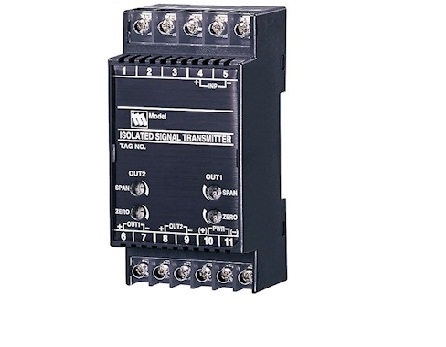
FRONT VIEW
EXTERNAL DIMENSIONS & TERMINAL ASSIGNMENTS unit: mm (inch)
SCHEMATIC CIRCUITRY & CONNECTION DIAGRAM
M-System Việt Nam Email: Sales@m-system.com.vn
|