M5PT VOILTAGE TRANSMITTER
Functions & Features
• Converts an alternating voltage from a potential (voltage) transformer into a standard process signal
• True RMS sensing
• High-density mounting
• Power LED
MODEL: M5PT-[1][2]-[3][4]
ORDERING INFORMATION
• Code number: M5PT-[1][2]-[3][4]
Specify a code from below for each [1] through [4].
(e.g. M5PT-14W-R/Q)
• Special output range (For codes Z & 0)
• Specify the specification for option code /Q
(e.g. /C01/S01)
[1] INPUT
Voltage
1: 0 – 110 V AC
2: 0 – 220 V AC
5: 0 – 150 V AC
[2] OUTPUT
Current
A: 4 – 20 mA DC (Load resistance 550 Ω max.)
Z: Specify current (See OUTPUT SPECIFICATIONS)
Voltage
4: 0 – 10 V DC (Load resistance 1000 Ω min.)
5: 0 – 5 V DC (Load resistance 500 Ω min.)
6: 1 – 5 V DC (Load resistance 500 Ω min.)
4W: -10 – +10 V DC (Load resistance 8000 Ω min.)
5W: -5 – +5 V DC (Load resistance 4000 Ω min.)
0: Specify voltage (See OUTPUT SPECIFICATIONS)
[3] POWER INPUT
AC Power
M: 85 – 264 V AC (Operational voltage range 85 – 264 V,
47 – 66 Hz)
DC Power
R: 24 V DC
(Operational voltage range 24 V ±10 %, ripple 10 %p-p max.)
[4] OPTIONS
blank: none
/Q: With options (specify the specification)
SPECIFICATIONS OF OPTION: Q (multiple selections)
COATING (For the detail, refer to M-System's web site.)
/C01: Silicone coating
/C02: Polyurethane coating
/C03: Rubber coating
TERMINAL SCREW MATERIAL
/S01: Stainless steel
GENERAL SPECIFICATIONS
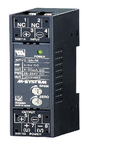
Construction: Terminal block
Connection: M3.5 screw terminals (torque 0.8 N·m)
Screw terminal: Nickel-plated steel (standard) or stainless steel
Housing material: Flame-resistant resin (black)
Isolation: Input to output to power
Input waveform
RMS sensing: Up to 15 % of 3rd harmonic content
Overrange output: Approx. 0 to 110 % at 1 – 5 V
Zero adjustment: -2 to +2 % (front)
Span adjustment: 98 to 102 % (front)
Power LED: Green LED turns on when the power is supplied.
INPUT SPECIFICATIONS
Frequency: 50 or 60 Hz
Input burden: 0.5 VA max.
Overload capacity: 200 % of rating for 1 min., 120 % continuous
Operational range: 5 – 120 % of rating
OUTPUT SPECIFICATIONS
■ DC Current: 0 – 20 mA DC
Minimum span: 1 mA
Offset: Max. 1.5 times span
Load resistance: Output drive 11 V max.
■ DC Voltage: 0 – 10 V DC
Minimum span: 1 V
Offset: Max. 1.5 times span
Load resistance: Output drive 10 mA max.; at ≥ 1 V
INSTALLATION
Power Consumption
•AC:
Approx. 2 VA at 100 V
Approx. 3 VA at 200 V
Approx. 3 VA at 264 V
•DC: Approx. 2 W
Operating temperature: -5 to +55°C (23 to 131°F)
Operating humidity: 0 to 90 %RH (non-condensing)
Mounting: DIN rail
Weight: 80 g (2.8 oz)
PERFORMANCE in percentage of span
Accuracy: ±0.3 % with input 5 – 100 %
(Input 10 – 100 % for the output codes 4W and 5W)
Temp. coefficient: ±0.02 %/°C (±0.01 %/°F)
Response time: ≤ 0.5 sec. (0 – 90 %)
Ripple: 0.5 %p-p max.
Line voltage effect: ±0.1 % over voltage range
Insulation resistance: ≥ 100 MΩ with 500 V DC
Dielectric strength (input to output to power to ground)
DC powered: 2000 V AC @1 minute
AC powered: 1500 V AC @1 minute
FRONT VIEW
EXTERNAL DIMENSIONS & TERMINAL ASSIGNMENTS unit: mm (inch)
SCHEMATIC CIRCUITRY & CONNECTION DIAGRAM
M-System Việt Nam Email: Sales@m-system.com.vn
|