M2FV SIGNAL TRANSMITTER
(field-configurable)
Functions & Features
• Converts DC input from a sensor into a standard process signal
• DIP switch configurable input & output range and response time
• High-density mounting
• Power indicator LED
Typical Applications
• Isolation between control room and field instrumentation
MODEL: M2FV-[1][2]
ORDERING INFORMATION
• Code number: M2FV-[1][2]
Specify a code from below for each [1] and [2].
(e.g. M2FV-M2/CE/Q)
• Specify the specification for option code /Q
(e.g. /C01/S01)
Orders will be shipped at default factory settings for Input (4 – 20mA ) and Output (4 – 20mA ) and Response time (Standard responce ).
INPUT – Field-selectable
Current
4 – 20 mA DC (Input resistance 50 Ω)
0 – 20 mA DC (Input resistance 50 Ω)
Voltage
0 – 10 V DC (Input resistance 100 kΩ min.)
2 – 10 V DC (Input resistance 100 kΩ min.)
0 – 5 V DC (Input resistance 100 kΩ min.)
1 – 5 V DC (Input resistance 100 kΩ min.)
OUTPUT – Field-selectable
Current
4 – 20 mA DC (Load resistance 750 Ω max.)
0 – 20 mA DC (Load resistance 750 Ω max.)
Voltage
0 – 10 V DC (Load resistance 10 kΩ min.)
2 – 10 V DC (Load resistance 10 kΩ min.)
0 – 5 V DC (Load resistance 5000 Ω min.)
1 – 5 V DC (Load resistance 5000 Ω min.)
[1] POWER INPUT
AC Power
M: 85 – 264 V AC (Operational voltage range 85 – 264 V,
47 – 66 Hz)
(Select ‘/N’ for ‘Standards & Approvals’ code.)
M2: 100 – 240 V AC (Operational voltage range 85 – 264 V,
47 – 66 Hz)
DC Power
R: 24 V DC
(Operational voltage range 24 V ±10 %, ripple 10 %p-p max.)
R2: 11 – 27 V DC
(Operational voltage range 11 – 27 V, ripple 10 %p-p max.)
(Select ‘/N’ for ‘Standards & Approvals’ code.)
P: 110 V DC
(Operational voltage range 85 – 150 V, ripple 10 %p-p max.)
[2] OPTIONS (multiple selections)
Standards & Approvals (must be specified)
/N: Without CE
/CE: CE marking
Other Options
blank: none
/Q: Option other than the above (specify the specification)
SPECIFICATIONS OF OPTION: Q (multiple selections)
COATING (For the detail, refer to M-System's web site.)
/C01: Silicone coating
/C02: Polyurethane coating
/C03: Rubber coating
TERMINAL SCREW MATERIAL
/S01: Stainless steel
GENERAL SPECIFICATIONS
Construction: Plug-in
Connection: M3 screw terminals (torque 0.8 N·m)
Screw terminal: Chromated steel (standard) or stainless steel
Housing material: Flame-resistant resin (black)
Isolation: Input to output to power
Overrange output: Approx. -10 to +120 %
Zero adjustment: -2 to +2 % (front)
Span adjustment: 98 to 102 % (front)
Power LED: Green light turns on when the power is supplied.
INPUT SPECIFICATIONS
■ DC Current: Input resistor incorporated
INSTALLATION
Power Consumption
•AC:
Approx. 3 VA at 100 V
Approx. 4 VA at 200 V
Approx. 5 VA at 264 V
•DC: Approx. 3 W
Operating temperature: -30 to +60°C (-22 to +140°F)
Operating humidity: 30 to 90 %RH (non-condensing)
Mounting: Surface or DIN rail
Weight: 150 g (0.33 lb)
PERFORMANCE in percentage of span
Accuracy: ±0.1 %
I/O setting accuracy: ±0.2 %
Temp. coefficient: ±0.015%/°C (±0.008%/°F)
Response time:
Standard response ≤ 0.5 sec. (0 – 90 %)
Fast response ≤ 30 msec. (0 – 90 %)
Line voltage effect: ±0.1 % over voltage range
Insulation resistance: ≥ 100 MΩ with 500 V DC
Dielectric strength: 2000 V AC @1 minute (input to output to power to ground)
STANDARDS & APPROVALS
EU conformity:
EMC Directive
EMI EN 61000-6-4
EMS EN 61000-6-2
Low Voltage Directive
EN 61010-1
Measurement Category II
Pollution Degree 2
Input or output to power: Reinforced insulation (300 V)
Input to output: Basic insulation (300 V)
RoHS Directive
EN 50581
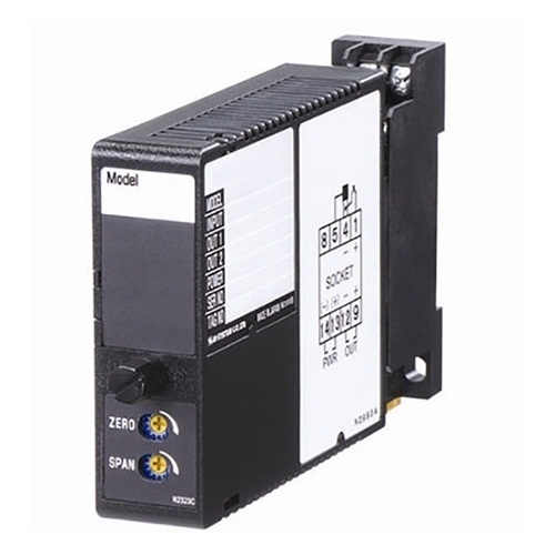
EXTERNAL VIEW
Refer to the instruction manual for detailed procedures.
DIMENSIONS unit: mm (inch)
SCHEMATIC CIRCUITRY & CONNECTION DIAGRAM
M-System Việt Nam Email: Sales@m-system.com.vn
|