|
|
|
M-SYSTEM >> Signal Conditioners |
| |
| Cập nhật: 2/10/2020 - Số lượt đọc: 3717 |
|
|
|
M6SCTC M6NCTC M6DCTC CURRENT TRANSMITTER
(clamp-on current sensor)
Functions & Features
• Maintenance-free tension clamp connection
• Converts AC current signal into a low-ripple standard process signal suitable to be handled for computer inputs
• 5.9-mm wide ultra-slim design
• Low profile allows the M6S module mounted in a 120-mm deep panel
• High-density mounting
• Power indicator LED
MODEL: M6SCTC–[1][2]–R[3]
ORDERING INFORMATION
• Code number: M6SCTC-[1][2]-R[3]
Specify a code from below for each [1] through [3].
(e.g. M6SCTC-56004W-R/Q)
• Special output range (For codes Z & 0)
• Specify the specification for option code /Q
(e.g. /C01)
Order Clamp-on current sensor separately.
[1] INPUT
Sensor CLSE
5R5: 0 – 5 A AC
550: 0 – 50 A AC
5100: 0 – 100 A AC
5200: 0 – 200 A AC
5400: 0 – 400 A AC
5600: 0 – 600 A AC
Sensor CLSB (CE not available)
210: 0 – 10 A AC
215: 0 – 15 A AC
220: 0 – 20 A AC
230: 0 – 30 A AC
240: 0 – 40 A AC
250: 0 – 50 A AC
260: 0 – 60 A AC
275: 0 – 75 A AC
2100: 0 – 100 A AC
2125: 0 – 125 A AC
2150: 0 – 150 A AC
2175: 0 – 175 A AC
2200: 0 – 200 A AC
2225: 0 – 225 A AC
2250: 0 – 250 A AC
2300: 0 – 300 A AC
2350: 0 – 350 A AC
2400: 0 – 400 A AC
2500: 0 – 500 A AC
2600: 0 – 600 A AC
[2] OUTPUT
Current
A: 4 – 20 mA DC (Load resistance 550 Ω max.)
D: 0 – 20 mA DC (Load resistance 550 Ω max.)
G: 0 – 1 mA DC (Load resistance 11 kΩ max.)
Z: Specify current (See OUTPUT SPECIFICATIONS)
Voltage
3: 0 – 1 V DC (Load resistance 1000 Ω min.)
4: 0 – 10 V DC (Load resistance 10 kΩ min.)
5: 0 – 5 V DC (Load resistance 5000 Ω min.)
6: 1 – 5 V DC (Load resistance 5000 Ω min.)
4W: -10 – +10 V DC (Load resistance 20 kΩ min.)
5W: -5 – +5 V DC (Load resistance 10 kΩ min.)
0: Specify voltage (See OUTPUT SPECIFICATIONS)
POWER INPUT
DC Power
R: 24 V DC
(Operational voltage range 24 V ±10 %, ripple 10 %p-p max.)
[3] OPTIONS
blank: none
/Q: With options (specify the specification)
SPECIFICATIONS OF OPTION: Q
COATING (For the detail, refer to M-System's web site.)
/C01: Silicone coating
/C02: Polyurethane coating
RELATED PRODUCTS
• Clamp-on current sensor (model: CLSB)
• Clamp-on current sensor (model: CLSE)
(Select “CLSE-x/CE” to comply with CE for the combination with the sensor.)
GENERAL SPECIFICATIONS
Connection
Input and output: Tension clamp
Power input: Via the Installation Base (model: M6SBS)
or Tension clamp
Applicable wire size: 0.2 to 2.5 mm2, stripped length 8 mm
Housing material: Flame-resistant resin (black)
Isolation: Input to output to power
Input waveform
RMS sensing: Up to 15 % of 3rd harmonic content
Zero adjustment: -2 to +2 % (front)
(Output code 4W, 5W: Adjustable at 0V. No output below
0 mA for the code D.)
Span adjustment: 98 to 102 % (front)
Power LED: Green light turns on when the power is supplied.
INPUT SPECIFICATIONS
■ Clamp-on current sensor CLSE
(Sensor model No.: AC input)
CLSE-R5: 0 – 5 A
CLSE-05: 0 – 50 A
CLSE-10: 0 – 100 A
CLSE-20: 0 – 200 A
CLSE-40: 0 – 400 A
CLSE-60: 0 – 600 A
Frequency: 50 / 60 Hz
Operational range: 5 – 120 % of rating
Overload capacity:
CLSE-R5: 10 A continuous
CLSE-05: 60 A continuous
CLSE-10: 120 A continuous
CLSE-20: 240 A continuous
CLSE-40: 480 A continuous
CLSE-60: 720 A continuous
Be sure that the input voltage is of 480 V or less.
■ Clamp-on current sensor CLSB
(Sensor model No.: AC input)
CLSB-05:
0 – 10 A, 0 – 15 A, 0 – 20 A
0 – 30 A, 0 – 40 A, 0 – 50 A
CLSB-10:
0 – 60 A, 0 – 75 A, 0 – 100 A
CLSB-20:
0 – 125 A, 0 – 150 A, 0 – 175 A
0 – 200 A, 0 – 225 A, 0 – 250 A
CLSB-40:
0 – 300 A, 0 – 350 A, 0 – 400 A
CLSB-60:
0 – 500 A, 0 – 600 A
Frequency: 50 / 60 Hz
Operational range: 5 – 120 % of rating
Overload capacity:
CLSB-05: 100 A continuous
CLSB-10: 200 A continuous
CLSB-20: 300 A continuous
CLSB-40: 600 A continuous
CLSB-60: 720 A continuous
Be sure that the input voltage is of 440 V or less.
OUTPUT SPECIFICATIONS
■ DC Current: 0 – 20 mA DC
Minimum span: 1 mA
Offset: Max. 1.5 times span
Load resistance: Output drive 11 V max.
■ DC Voltage: 0 – 10 V DC
Minimum span: 1 V
Offset: Max. 1.5 times span
Load resistance: Output drive 1 mA max.; at ≥ 1 V
INSTALLATION
Power consumption: Approx. 0.5 W
Operating temperature: -20 to +55°C (-4 to +131°F)
Operating humidity: 30 to 90 %RH (non-condensing)
Mounting: Installation Base (model: M6SBS) or DIN rail
Weight: 60 g (2.1 oz)
PERFORMANCE in percentage of span
Accuracy: ±0.5 % with input 5 – 100 %
Temp. coefficient: ±0.015 %/°C (±0.008 %/°F)
Response time: ≤ 1 sec. (0 – 90 %)
Line voltage effect: ±0.1 % over voltage range
Insulation resistance: ≥ 100 MΩ with 500 V DC
Dielectric strength: 2000 V AC @1 minute (input to output to power to ground)
STANDARDS & APPROVALS
EU conformity:
EMC Directive
EMI EN 61000-6-4
EMS EN 61000-6-2
RoHS Directive
EN 50581
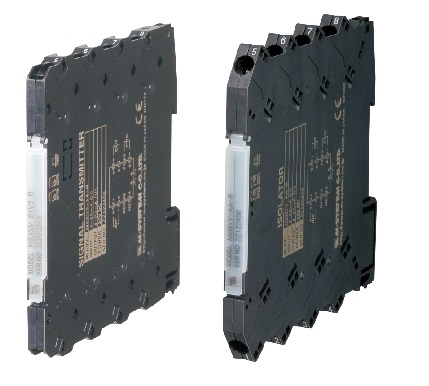
EXTERNAL VIEW
EXTERNAL DIMENSIONS & TERMINAL ASSIGNMENTS unit: mm (inch)
SCHEMATIC CIRCUITRY & CONNECTION DIAGRAM
M-System Việt Nam
Email: Sales@m-system.com.vn
|
| CÁC TIN KHÁC |
|
|
|
|
|
|
|
|
|
|
|
|
|
|
|
|
|
|
|
|
|
|
|
|
|
|
|
|
|
|
|
|
|
|
|
|
|
|
|
|
|
|
|
|
|
|
|
|
|
|
|
|
|
|
|
|
|
|
|
|
|
|
|
|
|
|
|
|
|
|
|
|
|
|
|
|
|
|
|
|
|
|
|
|
|
|
|
|
|
|
|
|
|
|
|
|
|
|

|
Lượt truy cập:
932540
|
|
Đang online:
4 |
|
|