W5FV SIGNAL TRANSMITTER
(field-configurable)
Functions & Features
• Converts a DC input into two isolated outputs
• Two independent output ranges
• DIP switch configurable input & output range
• Four-way isolation (input to output 1 to output 2 to power)
• High-density mounting
Typical Applications
• Isolation between control room and field instrumentation
MODEL: W5FV-[1]-[2][3]
ORDERING INFORMATION
• Code number: W5FV-[1]-[2][3]
Specify a code from below for each [1] through [3].
(e.g. W5FV-6-P/Q)
Orders will be shipped at default factory settings for Input (1 – 5V) and Output 1 (4 – 20mA ).
• Special 2nd output range (For codes Z & 0)
• Specify the specification for option code /Q
(e.g. /C01/S01)
INPUT – Field-selectable
Current
4 – 20 mA DC (Input resistance 250 Ω)
0 – 20 mA DC (Input resistance 250 Ω)
0 – 10 mA DC (Input resistance 250 Ω)
Voltage
0 – 60 mV DC (Input resistance 1 MΩ min.)
0 – 100 mV DC (Input resistance 1 MΩ min.)
0 – 1 V DC (Input resistance 1 MΩ min.)
0 – 10 V DC (Input resistance 1 MΩ min.)
0 – 5 V DC (Input resistance 1 MΩ min.)
1 – 5 V DC (Input resistance 1 MΩ min.)
-10 – +10 V DC (Input resistance 1 MΩ min.)
-5 – +5 V DC (Input resistance 1 MΩ min.)
OUTPUT 1 – Field-selectable
Current
4 – 20 mA DC (Load resistance 550 Ω max.)
0 – 20 mA DC (Load resistance 550 Ω max.)
Voltage
0 – 10 V DC (Load resistance 1000 Ω min.)
0 – 5 V DC (Load resistance 500 Ω min.)
1 – 5 V DC (Load resistance 500 Ω min.)
-10 – +10 V DC (Load resistance 8000 Ω min.)
-5 – +5 V DC (Load resistance 4000 Ω min.)
[1] OUTPUT 2
Y: None
Current
A: 4 – 20 mA DC (Load resistance 550 Ω max.)
B: 2 – 10 mA DC (Load resistance 1100 Ω max.)
C: 1 – 5 mA DC (Load resistance 2200 Ω max.)
D: 0 – 20 mA DC (Load resistance 550 Ω max.)
E: 0 – 16 mA DC (Load resistance 685 Ω max.)
F: 0 – 10 mA DC (Load resistance 1100 Ω max.)
G: 0 – 1 mA DC (Load resistance 11 kΩ max.)
Z: Specify current (See OUTPUT SPECIFICATIONS)
Voltage
1: 0 – 10 mV DC (Load resistance 10 kΩ min.)
2: 0 – 100 mV DC (Load resistance 100 kΩ min.)
3: 0 – 1 V DC (Load resistance 100 Ω min.)
4: 0 – 10 V DC (Load resistance 1000 Ω min.)
5: 0 – 5 V DC (Load resistance 500 Ω min.)
6: 1 – 5 V DC (Load resistance 500 Ω min.)
4W: -10 – +10 V DC (Load resistance 2000 Ω min.)
5W: -5 – +5 V DC (Load resistance 1000 Ω min.)
0: Specify voltage (See OUTPUT SPECIFICATIONS)
[2] POWER INPUT
AC Power
M: 85 – 264 V AC (Operational voltage range 85 – 264 V,
47 – 66 Hz)
(CE not available)
DC Power
R: 24 V DC
(Operational voltage range 24 V ±10 %, ripple 10 %p-p max.)
R2: 11 – 27 V DC
(Operational voltage range 11 – 27 V, ripple 10 %p-p max.)
(CE not available)
P: 110 V DC
(Operational voltage range 85 – 150 V, ripple 10 %p-p max.)
(CE not available)
[3] OPTIONS
blank: none
/Q: With options (specify the specification)
SPECIFICATIONS OF OPTION: Q (multiple selections)
COATING (For the detail, refer to M-System's web site.)
/C01: Silicone coating
/C02: Polyurethane coating
/C03: Rubber coating
TERMINAL SCREW MATERIAL
/S01: Stainless steel
GENERAL SPECIFICATIONS
Construction: Terminal block
Connection
Input: M3.5 screw terminals (torque 0.8 N·m)
Output & power: M3 screw terminals (torque 0.8 N·m)
Screw terminal: Nickel-plated steel (standard) or stainless steel
Housing material: Flame-resistant resin (black)
Isolation: Input to output 1 to output 2 to power
Overrange output: Approx. -10 to +120 % at 1 – 5 V
Zero adjustment: -2 to +2 % (front)
(±1 % with ±5 V and ±10 V input ranges)
Span adjustment: 98 to 102 % (front)
(99 to 101 % with ±5 V and ±10 V input ranges)
INPUT SPECIFICATIONS
■ DC Current: Input resistor incorporated
• DC Voltage
Input resistance: 1 MΩ min.
OUTPUT SPECIFICATIONS
OUTPUT 2
■ DC Current: 0 – 20 mA DC
Minimum span: 1 mA
Offset: Max. 1.5 times span
Load resistance: Output drive 11 V max.
■ DC Voltage: -10 – +12 V DC
Spans: Min. 5 mV, max. 20 V
Offset: Max. 1.5 times span
Load resistance: Output drive 10 mA max.; 5 mA for negative voltage output; at ≥ 0.5 V
INSTALLATION
Power Consumption
•AC:
Approx. 4 VA at 100 V
Approx. 5 VA at 200 V
Approx. 6 VA at 264 V
•DC: Approx. 3 W
Operating temperature: -5 to +55°C (23 to 131°F)
Operating humidity: 0 to 90 %RH (non-condensing)
Mounting: DIN rail
Weight: 130 g (0.29 lb)
PERFORMANCE in percentage of span
Accuracy: ±0.1 %
Temp. coefficient: ±0.015 %/°C (±0.008 %/°F)
Response time: ≤ 0.5 sec. (0 – 90 %)
Line voltage effect: ±0.1 % over voltage range
Insulation resistance: ≥ 100 MΩ with 500 V DC
Dielectric strength:
2000 V AC @1 minute (input to output 1 or output 2 to power to ground)
1000 V AC @1 minute (output 1 to output 2)
STANDARDS & APPROVALS
EU conformity:
EMC Directive
EMI EN 61000-6-4
EMS EN 61000-6-2
RoHS Directive
EN 50581
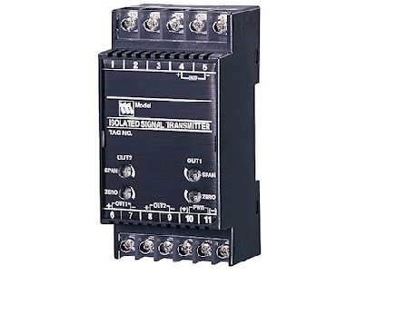
EXTERNAL VIEW
INPUT RANGE (DIP SW)
Input exceeding the maximum value of each input range may destroy the transmitter. Be sure to confirm the setting range before applying input signals.
Input range setting accuracy: Approx. 1 % (≤ 2 % when both input and output ranges are modified.)
OUTPUT RANGE (DIP SW)
Only Output 1 is field-configurable. Specify Output 2 range
when ordering.
Output range setting accuracy: Approx. 1 % (≤ 2 % when both input and output ranges are modified.)
EXTERNAL DIMENSIONS & TERMINAL ASSIGNMENTS unit: mm (inch)
SCHEMATIC CIRCUITRY & CONNECTION DIAGRAM
M-System Việt Nam Email: Sales@m-system.com.vn
|