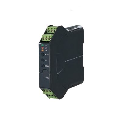
M3LV SIGNAL TRANSMITTER
(field- and PC-configurable)
Functions & Features
• Accepts a DC mV, V or mA input and provides
an isolated DC signal
• Easy ‘One-Step Cal’ calibration using the front three control buttons without needing a PC; PC software is also usable.
• Both input and output type and range are configurable
• Front control button function can be locked
Typical Applications
• Signal conversion between control room and field instrumentation with isolation
• Ideal for use as a fast solution, multifunctional spare part
MODEL: M3LV–R4/[1][2]
ORDERING INFORMATION
• Code number: M3LV-R4/[1][2]
Specify a code from below for each [1] and [2].
(e.g. M3LV-R4/A/UL/Q)
• Specify the specification for option code /Q
(e.g. /C01)
Orders will be shipped with default factory settings (4 – 20 mA input / 4 – 20 mA output).
INPUT – Field-selectable
DC Current & Voltage
Current: 0 – 20 mA DC
Millivolt: -1000 – +1000 mV DC
Voltage: -10 – +10 V DC
OUTPUT – Field-selectable
Current
0 – 20 mA DC
Voltage
-2.5 – +2.5 V DC
-10 – +10 V DC
POWER INPUT
DC Power
R4: 10 – 32 V DC
(Operational voltage range 9 - 36 V, ripple 10 %p-p max.)
[1] CONFIGURATION OPTIONS
A: PC and field configurable
B: Field configurable
[2] OPTIONS (multiple selections)
Standards & Approvals
blank: CE marking
/UL: UL approval, CE marking
Other Options
blank: none
/Q: Option other than the above (specify the specification)
SPECIFICATIONS OF OPTION: Q
COATING (For the detail, refer to M-System's web site.)
/C01: Silicone coating
/C02: Polyurethane coating
/C03: Rubber coating (UL not available)
RELATED PRODUCTS
• PC configurator software (model: M3CFG)
Downloadable at M-System’s web site.
A dedicated cable is required to connect the module to the PC. Please refer to the internet software download site or the users manual for the PC configurator for applicable cable types.
GENERAL SPECIFICATIONS
Construction: Small-sized front terminal structure
Connection: Euro type connector terminal
(applicable wire size: 0.2 to 2.5 mm2, stripped length 8 mm)
Housing material: Flame-resistant resin (gray)
Isolation: Input to output to power
Overrange output: -15 to +115 %
Zero adjustment: -15 to +15 % (front)
Span adjustment: 85 to 115 % (front)
Status indicator LED: Tri-color (green/amber/red) LED; Blinking patterns indicate operation status of the transmitter.
Configuration
PC Configurator: (Model: M3LVCFG) via Windows PC connected to th front jack.
Programmable features include:
• I/O type and range
• Zero and span adjustments
• User’s linearization table setting
(max. 101 points, specified within -15 to +115 % for both input and output)
(Refer to the instruction manual)
‘One-Step Cal’ calibration: With I/O type and the full-scale range configured via the internal DIP switches, precise 0 % and 100 % ranges are calibrated via the front control buttons with a help of LED. Also I/O calibration and fine adjustment are available with a PC.
Configurator connection: 2.5 dia. miniature jack;
RS-232-C level
INPUT SPECIFICATIONS
■ DC Current: 49.9 Ω resistor incorporated
Maximum range: 0 – 20 mA DC
Minimum span: 2 mA
Offset: Lower range can be any specific value within the input range provided that the minimum span is maintained.
■ DC mV & Voltage
•Narrow Spans (mV)
Maximum range: -1000 mV – +1000 mV DC
Minimum span: 100 mV
•Wide Spans (V)
Maximum range: -10 – +10 V DC
Minimum span: 1 V
Offset: Lower range can be any specific value within the input range provided that the minimum span is maintained.
Input resistance: 1 MΩ minimum
OUTPUT SPECIFICATIONS
■ DC Current
Maximum range: 0 – 20 mA DC
Minimum span: 1 mA
Conformance range: 0 – 24 mA DC
(Negative overrange current below 0 mA is not available.)
Offset: Lower range can be any specific value within the output range provided that the minimum span is maintained.
Load resistance: Output drive 12 V maximum
■ DC Voltage
Narrow Spans
Maximum range: -2.5 – +2.5 V DC
Minimum span: 250 mV
Conformance range: -3 – +3 V DC
Wide Spans
Maximum range: -10 – +10 V DC
Minimum span: 1 V
Conformance range: -11.5 – +11.5 V DC
Offset: Lower range can be any specific value within the output range provided that the minimum span is maintained.
Load resistance: Output drive 1 mA maximum
INSTALLATION
Power consumption
•DC: Approx. 3 W
Operating temperature: -25 to +65°C (-13 to +149°F)
Max. 55°C (131°F) for UL approval
Operating humidity: 0 to 95 %RH (non-condensing)
Mounting: DIN rail
Weight: 100 g (3.53 oz)
PERFORMANCE
Accuracy: Input Accuracy + Output Accuracy
Input accuracy: (% of input range)
(Inversely proportional to the span.)
-1000 – +1000 mV : ±0.01 (%)
-10 – +10 V : ±0.01
0 – 20 mA : ±0.02
Output accuracy: ±0.04 % of output range
(Inversely proportional to the span.)
Temp. coefficient: ±0.015 %/°C (±0.008 %/°F) of max. span
Response time: ≤ 0.5 sec. (0 – 90 %)
Line voltage effect: ±0.1 % over voltage range
Insulation resistance: ≥ 100 MΩ with 500 V DC
Dielectric strength: 1500 V AC @ 1 minute
(input to output or power to ground)
500 V AC @ 1 minute (output to power)
CALCULATION EXAMPLES OF OVERALL ACCURACY
[Example] Input Signal 1 – 5 V, Output Signal 1 – 5 V
Max. Input Range (20 V) ÷ Span (4 V) × 0.01 % +
Max. Output Range (20 V) ÷ Span (4 V) × 0.04 % = 0.25 %
STANDARDS & APPROVALS
EU conformity:
EMC Directive
EMI EN 61000-6-4
EMS EN 61000-6-2
RoHS Directive
EN 50581
Approval:
UL/C-UL general safety requirements
(UL 61010-1, CAN/CSA-C22.2 No.1010-1)
EXTERNAL VIEW
The DIP switch setting is required to select output types before setting a precise output range using the PC configurator software.
For detailed information on the configuration and calibration, refer to the instruction manual.
EXTERNAL DIMENSIONS & TERMINAL ASSIGNMENTS unit: mm (inch)
SCHEMATIC CIRCUITRY & CONNECTION DIAGRAM
M-System Việt Nam Email: Sales@m-system.com.vn
|