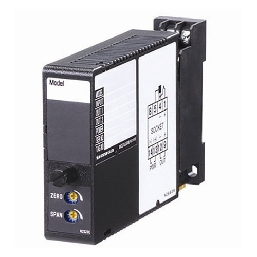
W2AC AC TRANSMITTER
Functions & Features
• Converts an alternating current/voltage input into a standard process signal
• True RMS sensing
• Two independent output ranges
Typical Applications
• Converting high AC current in combination with a shunt resistor, or narrow span AC voltage
MODEL: W2AC–[1][2][3]-[4][5]
ORDERING INFORMATION
• Code number: W2AC-[1][2][3]-[4][5]
Specify a code from below for each [1] through [5].
(e.g. W2AC-A1AA-M2/CE/Q)
• Special input and output ranges (For codes AZ, A8, Z & 0)
• Specify the specification for option code /Q
(e.g. /C01/S01)
Note: If one of the outputs should be a current range, specify it for the Output 1 to allow a greater load.
[1] INPUT
Current
AA: 0 – 10 mA AC (Input resistance 100 Ω)
AB: 0 – 50 mA AC (Input resistance 20 Ω)
AC: 0 – 100 mA AC (Input resistance 10 Ω)
AD: 0 – 500 mA AC (Input resistance 1 Ω)
AZ: Specify current (See INPUT SPECIFICATIONS)
(0 % input must be 0 mA.)
Voltage
A1: 0 – 100 mV AC (Input resistance Approx. 100 kΩ min.)
A2: 0 – 500 mV AC (Input resistance Approx. 100 kΩ min.)
A3: 0 – 1 V AC (Input resistance Approx. 100 kΩ min.)
A4: 0 – 5 V AC (Input resistance Approx. 100 kΩ min.)
A5: 0 – 10 V AC (Input resistance Approx. 100 kΩ min.)
A6: 0 – 120 V AC (Input resistance Approx. 100 kΩ min.)
A7: 0 – 150 V AC (Input resistance Approx. 100 kΩ min.)
A8: Specify voltage (See INPUT SPECIFICATIONS)
(0 % input must be 0 V.)
[2] OUTPUT 1
Current
A: 4 – 20 mA DC (Load resistance 750 Ω max.)
B: 2 – 10 mA DC (Load resistance 1500 Ω max.)
C: 1 – 5 mA DC (Load resistance 3000 Ω max.)
D: 0 – 20 mA DC (Load resistance 750 Ω max.)
E: 0 – 16 mA DC (Load resistance 900 Ω max.)
F: 0 – 10 mA DC (Load resistance 1500 Ω max.)
G: 0 – 1 mA DC (Load resistance 15 kΩ max.)
Z: Specify current (See OUTPUT SPECIFICATIONS)
Voltage
1: 0 – 10 mV DC (Load resistance 10 kΩ min.)
2: 0 – 100 mV DC (Load resistance 100 kΩ min.)
3: 0 – 1 V DC (Load resistance 1000 Ω min.)
4: 0 – 10 V DC (Load resistance 10 kΩ min.)
5: 0 – 5 V DC (Load resistance 5000 Ω min.)
6: 1 – 5 V DC (Load resistance 5000 Ω min.)
4W: -10 – +10 V DC (Load resistance 10 kΩ min.)
5W: -5 – +5 V DC (Load resistance 5000 Ω min.)
0: Specify voltage (See OUTPUT SPECIFICATIONS)
[3] OUTPUT 2
Y: None
Current
A: 4 – 20 mA DC (Load resistance 350 Ω max.)
B: 2 – 10 mA DC (Load resistance 700 Ω max.)
C: 1 – 5 mA DC (Load resistance 1400 Ω max.)
D: 0 – 20 mA DC (Load resistance 350 Ω max.)
E: 0 – 16 mA DC(Load resistance 430 Ω max.)
F: 0 – 10 mA DC (Load resistance 700 Ω max.)
G: 0 – 1 mA DC (Load resistance 7000 Ω max.)
Z: Specify current (See OUTPUT SPECIFICATIONS)
Voltage
Same range availability as Output 1
[4] POWER INPUT
AC Power
M2: 100 – 240 V AC (Operational voltage range 85 – 264 V,
47 – 66 Hz)
(90 – 264 V for UL)
DC Power
R: 24 V DC
(Operational voltage range 24 V ±10 %, ripple 10 %p-p max.)
R2: 11 – 27 V DC
(Operational voltage range 11 – 27 V, ripple 10 %p-p max.)
(Select ‘/N’ for ‘Standards & Approvals’ code.)
P: 110 V DC
(Operational voltage range 85 – 150 V, ripple 10 %p-p max.)
(110 V ±10 % for UL)
[5] OPTIONS (multiple selections)
Standards & Approvals (must be specified)
/N: Without CE or UL
/CE: CE marking
/UL: UL approval, CE marking
Other Options
blank: none
/Q: Option other than the above (specify the specification)
SPECIFICATIONS OF OPTION: Q (multiple selections)
COATING (For the detail, refer to M-System's web site.)
/C01: Silicone coating
/C02: Polyurethane coating
/C03: Rubber coating (UL not available)
TERMINAL SCREW MATERIAL
/S01: Stainless steel (UL not available)
GENERAL SPECIFICATIONS
Construction: Plug-in
Connection: M3 screw terminals (torque 0.8 N·m)
Screw terminal: Chromated steel (standard) or stainless steel
Housing material: Flame-resistant resin (black)
Isolation: Input to output 1 to output 2 to power
Input waveform
RMS sensing: Up to 15 % of 3rd harmonic content
Overrange output: 0 to 120 % at 1 – 5 V
Zero adjustment: -5 to +5 % (front)
Span adjustment: 95 to 105 % (front)
Adjustable individually for each output 1 and output 2.
INPUT SPECIFICATIONS
Frequency: 40 Hz min., 1 kHz max.
■ AC Current: 0 – 1 A AC; input resistor incorporated
Minimum span: 1 mA
Input resistance
Span 1 mA: 1 kΩ
Span ≤ 2 mA: 500 Ω
Span ≤ 5 mA: 200 Ω
Span ≤ 10 mA: 100 Ω
Span ≤ 20 mA: 50 Ω
Span ≤ 50 mA: 20 Ω
Span ≤ 100 mA: 10 Ω
Span ≤ 500 mA: 1 Ω
Span ≤ 1 A: 0.5 Ω
■ AC Voltage: 0 – 250 V AC
Minimum span: 50 mV
Input resistance: Approx. 100 kΩ min.
OUTPUT SPECIFICATIONS
■ DC Current: 0 – 20 mA DC
Minimum span: 1 mA
Offset: Max. 1.5 times span
Load resistance: Output drive 15 V max. for Output 1;
7 V max. for Output 2
■ DC Voltage: -10 – +12 V DC (up to 10 V for Output 2)
Minimum span: 5 mV
Offset: Max. 1.5 times span
Load resistance: Output drive 1 mA max.; at ≥ 0.5 V
INSTALLATION
Power Consumption
•AC:
Approx. 4 VA at 100 V
Approx. 5 VA at 200 V
Approx. 6 VA at 240 V
•DC: Approx. 3 W
Operating temperature: -5 to +55°C (23 to 131°F)
Operating humidity: 30 to 90 %RH (non-condensing)
Mounting: Surface or DIN rail
Weight: 200 g (0.44 lb)
PERFORMANCE in percentage of span
Accuracy: ±0.4 %
Temp. coefficient: ±0.05 %/°C (±0.03 %/°F)
Response time: ≤ 0.7 sec. (0 – 90 %)
Ripple: 0.5 %p-p max. (50/60 Hz)
Line voltage effect: ±0.1 % over voltage range
Insulation resistance: ≥ 100 MΩ with 500 V DC
Dielectric strength: 2000 V AC @1 minute (input to output
1 to output 2 to power to ground)
STANDARDS & APPROVALS
EU conformity:
EMC Directive
EMI EN 61000-6-4
EMS EN 61000-6-2
Low Voltage Directive
EN 61010-1
Installation Category II
Pollution Degree 2
Input or output 1 or output 2 to power input:
Reinforced insulation (300 V)
Input to output 1 to output 2: Basic insulation (300 V)
RoHS Directive
EN 50581
Approval:
UL/C-UL nonincendive Class I, Division 2,
Groups A, B, C, and D
(ANSI/ISA-12.12.01, CAN/CSA-C22.2 No.213)
UL/C-UL general safety requirements
(UL 61010-1, CAN/CSA-C22.2 No.61010-1)
EXTERNAL DIMENSIONS & TERMINAL ASSIGNMENTS unit: mm (inch)
SCHEMATIC CIRCUITRY & CONNECTION DIAGRAM
M-System Việt Nam Email: Sales@m-system.com.vn
|