·Some details are not shown. Please refer to specification sheets for all information.
JC-HL
Remote I/O JC Series
HUB MODULE
MODEL: JC–HL-[1]-1[2]-[3][4]
ORDERING INFORMATION • Code number: JC-HL-[1]-1[2]-[3][4] Specify a code from below for each [1] through [4]. (e.g. JC-HL-7-12-R/H/Q) • Specify the specification for option code /Q (e.g. /SET)
[1] I/O TYPE 3: 3 port (trunk 1 port, feeder 2 port) 7: 7 port (trunk 1 port, feeder 6 port)
TERMINAL BLOCK 1: Tension clamp terminal block for power supply RJ-45 Modular jack for communication
[2] COMMUNICATION CONNECTOR PIN ASSIGNMENT 1: 3, 4 - 5, 6 pair wiring (M-System HLS related products standard pin assignment) 2: 4, 5 - 3, 6 pair wiring (Ethernet LAN cable pin assignment)
[3] POWER INPUT DC Power R: 24 V DC (Operational voltage range 24 V ±10 %, ripple 10 %p-p max.) R5: 16 - 32 V DC (Operational voltage range 15 - 33 V DC, ripple 10 %p-p max.)
[4] OPTIONS (multiple selections) Communication Mode blank: Full-duplex /H: Half-duplex Other Options blank: none /Q: Option other than the above (specify the specification)
SPECIFICATIONS OF OPTION: Q EX-FACTORY SETTING /SET: Preset according to the Ordering Information Sheet (No. ESU-9041)
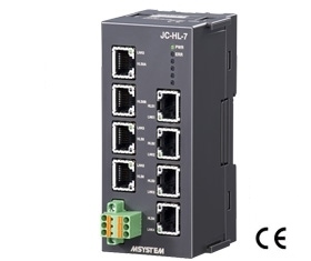
FUNCTIONS & FEATURES The HUB Module for HLS (model: JC-HL) extends total length of network cable and branch cable of HLS (Hi-speed Link System). Total max. length is 2.4 km when transfer rate is 3 Mbps. In order to connect the JC-HL, the master unit configuring HLS must support HUB module.
HLS is the abbreviation for “Hi-speed Link System” of Step Technica Co., Ltd.
RELATED PRODUCTS • High-speed link system I/O modules (model: R7F4DH, R7K4DH, R7HL, R7FN etc.) • MP2200/MP2300 series use HLS master module (model: MPHLS)
GENERAL SPECIFICATIONS Number of port: JC-HL-3: Trunk 1 port, feeder 2 port JC-HL-7: Trunk 1 port, feeder 6 port Max. number of inserted HUBs: 7 (Depending on specification of master unit) Connectable devices: The products conforming to HLS Connection Network: RJ-45 Modular Jack Power input: Separable tension clamp terminal Power on LED: PWR (green) turns on while the power is supplied.
HLS COMMUNICATION Communication mode: Full-duplex or half-duplex Network cable • Shield cable ZHY262PS (Shinko Seisen Industry Co., Ltd.) ZHT262PS (Shinko Seisen Industry Co., Ltd.) • Dual-shield cable ZHY262PBA (Shinko Seisen Industry Co., Ltd.) Transmission distance / Transfer rate: Refer to the table below (Selectable with DIP switch. Factory default: 12 Mbps) Terminating resistor: Trunk built-in (Selectable with DIP switch. Factory default: disable) Feeder built-in Status indicator LEDs: ERR, LNK (Refer to the instruction manual for details)
INSTALLATION Rated current for power supply connector: 8A Power consumtpion: JC-HL-3: Approx. 1 W JC-HL-7: Approx. 1.4 W Operating temperature: -10 to +55°C Operating humidity: 10 to 90 %RH (non-condensing) Atmosphere: No corrosive gas or heavy dust Mounting: Surface or DIN rail Weight JC-HL-3: 150 g (0.33 lb) JC-HL-7: 160 g (0.35 lb)
PERFORMANCE Insulation resistance: ≥ 100 MΩ with 500 V DC JC-HL-3 (HLS0A or HLS0B to HLS1 or HLS2 or FE to power) JC-HL-7 (HLS0A or HLS0B to HLS1 or HLS2 or HLS3 or HLS4 or HLS5 or HLS6 or FE to power) Dielectric strength: 1500 V AC @ 1 minute JC-HL-3 (HLS0A or HLS0B to HLS1 or HLS2 or FE to power) JC-HL-7 (HLS0A or HLS0B to HLS1 or HLS2 or HLS3 or HLS4 or HLS5 or HLS6 or FE to power)
STANDARDS & APPROVALS Refer to the manuals to comply with the standards. EU conformity: EMC Directive EMI EN 61000-6-4 EMS EN 61000-6-2 RoHS Directive EN 50581
MOUNTING REQUIREMENTS mm (inch)
EXTERNAL VIEW
CONNECTION DIAGRAMS
DIMENSIONS unit: mm (inch)
SCHEMATIC CIRCUITRY Note: In order to improve EMC performance, bond the FE terminal to ground. Caution: FE terminal is NOT a protective conductor terminal.