·Some details are not shown. Please refer to specification sheets for all information.
R30SV4
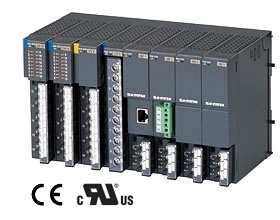
Remote I/O R30 Series
DC VOLTAGE/CURRENT INPUT MODULE (4 points, isolated)
Functions & Features • 4 channels for DC voltage/current input remote I/O module • Isolation between input channels • Input range of each channel is individually adjustable with PC configurator
MODEL: R30SV4S[1]
ORDERING INFORMATION • Code number: R30SV4S[1] Specify a code from below for [1]. (e.g. R30SV4S/Q) • Specify the specification for option code /Q (e.g. /C01/SET)
NO. OF CHANNELS 4: 4
COMMUNICATION MODE S: Single
[1] OPTIONS blank: none /Q: With options (specify the specification)
SPECIFICATIONS OF OPTION: Q (multiple selections) COATING (For the detail, refer to M-System's web site.) /C01: Silicone coating /C02: Polyurethane coating /C03: Rubber coating EX-FACTORY SETTING /SET: Preset according to the Ordering Information Sheet (No. ESU-9001)
CAUTION ■ UNUSED INPUT CHANNELS Set unused channels to "CH disabled" with PC Configurator software: R30CFG. When input range is 1 to 5 V DC or 4 to 20 mA DC, input values of the unused channels left open are to be lower than -15 %, which set a data error at the PLC or other host devices.
RELATED PRODUCTS • PC configurator software (model: R30CFG) Downloadable at M-System’s web site. For connecting to PC, use commercially available Mini-B type USB cable. (provided by user)
GENERAL SPECIFICATIONS Connection Internal bus: Via the Installation Base (model: R30BS) Input: M3 separable screw terminal (torque 0.5 N·m) Internal power supply: Via the Installation Base (model: R30BS) Solderless terminal: Refer to the drawing at the end of the section. Recommended manufacturer: Japan Solderless Terminal MFG. Co., Ltd., Nichifu Co., Ltd. (Solderless terminals with insulation sleeve do not fit.) Applicable wire size: 0.25 to 0.75 mm2 Screw terminal: Nickel-plated steel Isolation: Input 1 to input 2 to input 3 to input 4 to internal bus or internal power Input range: Selectable with PC configuration software (model: R30CFG) Conversion rate: Selectable with PC configuration software (model: R30CFG) Status indicator LED: RUN, ERR (refer to the instruction manual)
INPUT SPECIFICATIONS Module type: Analog input, 4 points ■ DC Current Input resistor: 70 Ω Input range: :-20 to +20 mA DC, 0 to 20 mA DC, 4 to 20 mA DC ■ Narrow span voltage Input resistance: ≥ 100 kΩ Input range: :-1 to +1 V DC, 0 to 1 V DC, -0.5 to +0.5 V DC ■ Wide span voltage Input resistance: ≥ 1 MΩ Input range: :-10 to +10 V DC (*), -5 to +5 V DC, 0 to 10 V DC, 0 to 5 V DC, 1 to 5 V DC (*) Factory setting
INSTALLATION Current consumption: 50 mA Operating temperature: -10 to +55°C (14 to 131°F) Storage temperature: -20 to +65°C (-4 to +149°F) Operating humidity: 10 to 90 %RH (non-condensing) Atmosphere: No corrosive gas or heavy dust Mounting: Installation Base (model: R30BS) Weight: 160 g (0.35 lb)
PERFORMANCE Conversion rate / conversion accuracy: 10 ms / ±0.8%, 20 ms / ±0.4%, 40 ms / ±0.2%, 80 ms / ±0.1% (*) (*) Factory setting Data range: 0 – 10000 of the input range Data allocation: 4 Temp. coefficient: ±0.015 %/°C (±0.008 %/°F) Input delay time: 50 ms Insulation resistance: ≥ 100 MΩ with 500 V DC Dielectric strength: 1500 V AC @ 1 minute (input 1 to input 2 to input 3 to input 4 to internal bus or internal power) 1500 V AC @ 1 minute (power input to FE; isolated on the power supply module)
STANDARDS & APPROVALS EU conformity: EMC Directive EMI EN 61000-6-4 EMS EN 61000-6-2 RoHS Directive EN 50581
CONFIGURATOR SOFTWARE SETTING With configurator software, settings shown below are available. Refer to the software manual of R30CFG for detailed operation.
EXTERNAL VIEW
TERMINAL ASSIGNMENTS
EXTERNAL DIMENSIONS & TERMINAL ASSIGNMENTS unit: mm (inch)