·Some details are not shown. Please refer to specification sheets for all information.
R1C-GH
Remote I/O R1X Series
THERMOCOUPLE & DC INPUT MODULE (16 points; CC-Link Ver.1.10/Ver.2.00)
Functions & Features • 16-point thermocouple or DC inputs • CC-Link interface • CC-Link Version 1.10 and 2.00 can be switched at the startup
MODEL: R1C-GH2T-[1][2]
ORDERING INFORMATION • Code number: R1C-GH2T-[1][2] Specify a code from below for each [1] and [2]. (e.g. R1C-GH2T-M2/Q) • Specify the specification for option code /Q (e.g. /C01) • Use Ordering Information Sheet (No. ESU-5956). Default setting will be used if not otherwise specified. Factory default setting Input type: DC Voltage ±5 V Burnout protection: No burnout Cold junction compensation: No
FIELD TERMINAL TYPE T:M3 screw terminals
[1] POWER INPUT AC Power M2: 100 – 240 V AC (Operational voltage range 85 – 264 V, 47 – 66 Hz) DC Power R: 24 V DC (Operational voltage range 24 V ±10 %, ripple 10 %p-p max.)
[2] OPTIONS blank: none /Q: With options (specify the specification)
SPECIFICATIONS OF OPTION: Q COATING (For the detail, refer to M-System's web site.) /C01: Silicone coating /C02: Polyurethane coating /C03: Rubber coating
RELATED PRODUCTS • Resistor module (model: REM3-250) • R1X configurator software (model: R1CON) Downloadable at M-System’s web site. A dedicated cable is required to connect the module to the PC. Please refer to the internet software download site or the users manual for the PC configurator for applicable cable types.
GENERAL SPECIFICATIONS Connection Power input, CC-Link: Euro type connector terminal (applicable wire size: 0.2 to 2.5 mm2 (AWG24 to 12), stripped length 7 mm) Input: M3 screw terminals (torque 0.6 N·m) Configurator: 2.5 dia. miniature jack; RS-232-C level Screw terminal: Nickel-plated steel Housing material: Flame-resistant resin (gray) Isolation: Input to CC-Link (FG) to power PWR indicator: Green LED blinks in normal conditions.
CC-Link COMMUNICATION Protocol: CC-Link V1.10 / V 2.00 Cable for comm. link: Specified by Mitsubishi Electric Required nodes V. 1.10: 4 V. 2.00: 1 (cyclic expansion: 4) Station No. setting: Rotary switch V. 1.10: Rotary switch; 1 – 61 V. 2.00: Rotary switch; 1 – 64 Baud rate setting: Rotary switch L RUN indicator: Red LED turns on in normal conditions. L ERR. indicator: Red LED turns on or blinks in an abnormality. SD indicator: Red LED turns on when transmitting. RD indicator: Red LED turns on when receiving.
INPUT SPECIFICATIONS ■ Thermocouple or DC input, 16 points (Common negative for DC input) •Measuring range ±20 V, ±5 V, ±1 V: Atten. SW ON (3) •Measuring range ±0.8 V, ±0.2 V, ±50 mV, ±10m V: Atten. SW OFF (1) Input resistance: 300 kΩ Thermocouple types: PR, K, E, J, T, B, R, S, C, N, U, L, P Sampling rate: 150 millisec./16 points ■ A/D conversion output: 16-bit signed binary (negative range represented by 2’s complements) Engineering unit value is converted into A/D conversion data as shown below. Input type & range: A/D data (decimal) ±20 V: ±20000 ±5 V: ±5000 ±1 V: ±10000 ±0.8 V: ±8000 ±0.2 V: ±20000 ±50 mV: ±5000 ±10 mV: ±10000 Thermocouples: Temperature × 10 In order to change input type and range after shipment, the R1X configurator software (model: R1CON) is required. CC-Link version selector input: Ver. 1.10 with OFF at the startup. Ver. 2.00 with ON at the startup. Dry contact input (ON at detect. level ≤ 1.5 V) Sensing: approx. 5 V DC, 1 mA Valid only at the moment of the power supplied to the module. Firmware version 0B.00 or higher required. Confirm the firmware version using the R1X configurator software (model: R1CON) or consult M-System.
INSTALLATION Power consumption •AC: Approx. 10 VA •DC: Approx. 7 W Operating temperature: -5 to +60°C (23 to 140°F) Operating humidity: 30 to 90 %RH (non-condensing) Mounting: Surface or DIN rail Weight: 400 g (0.88 lb)
PERFORMANCE (% of measuring range) Accuracy DC input: ±0.3 % Thermocouple input: See the table on the end of this section. Cold junction compensation error: ±3°C or ±5.4°F max. (at 20°C ±10°C or 68°F ±18°F) Temp. coefficient: ±0.015 %/°C (±0.008 %/°F) ±0.05 %/°C (±0.03 %/°F) for 10 mV range and T/C B (RH) Insulation resistance: ≥ 100 MΩ with 500 V DC Dielectric strength: 2000 V AC @ 1 minute (input to CC-Link [FG] to power to ground [FG1])
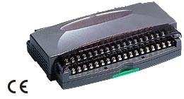
EXTERNAL VIEW
CONNECTION DIAGRAM
EXTERNAL DIMENSIONS & TERMINAL ASSIGNMENTS unit: mm (inch)