·Some details are not shown. Please refer to specification sheets for all information.
R5-MS
Remote I/O R5 Series
POTENTIOMETER INPUT MODULE
MODEL: R5-MS[1][2][3]
ORDERING INFORMATION • Code number: R5-MS[1][2][3] Specify a code from below for each [1] through [3]. (e.g. R5-MS2W/Q) • Specify the specification for option code /Q (e.g. /C01)
[1] NO. OF CHANNELS 1: 1 channel 2: 2 channels
[2] COMMUNICATION MODE S: Single W: Dual
[3] OPTIONS blank: none /Q: With options (specify the specification)
SPECIFICATIONS OF OPTION: Q COATING (For the detail, refer to M-System's web site.) /C01: Silicone coating /C02: Polyurethane coating /C03: Rubber coating
GENERAL SPECIFICATIONS Connection Internal bus: Via the Installation Base (model: R5-BS) Input: Euro type connector terminal (Applicable wire size: 0.2 – 2.5 mm2 (AWG24 - 12), stripped length 7 mm) Internal power: Via the base (model: R5-BS) Isolation: Input 1 to input 2 to internal bus or internal power Zero/Span adj. mode selector: Rotary switch; run mode and adj. mode selectable RUN indicator: Bi-color (red/green) LED; Red when the bus A operates normally; Green when the bus B operates normally; Amber when both buses operate normally.
INPUT SPECIFICATIONS Total resistance: 100 Ω – 10 kΩ Minimum span: 50 % of the total resistance range Excitation: 0.5 V DC
INSTALLATION Operating temperature: -10 to +55°C (14 to 131°F) Operating humidity: 30 to 90 %RH (non-condensing) Atmosphere: No corrosive gas or heavy dust Mounting: Installation Base (model: R5-BS) Weight: 100 g (3.53 oz)
PERFORMANCE Conversion accuracy: ±0.1 % Data range: 0 – 10000 of the input range Data allocation: 1 (2 for 2-channel type) Temp. coefficient: ±0.015 %/°C (±0.008 %/°F) Resolution: 1/10000 of the total resistance range (Reduced by the actual range determined zero/ span positions. Minimum 50 % of the total resistance range must be maintained.) Response time: ≤ 0.1 sec. (0 – 90 %) Insulation resistance: ≥ 100 MΩ with 500 V DC Dielectric strength: 1500 V AC @ 1 minute (input 1 to input 2 to internal bus or internal power) 2000 V AC @ 1 minute (power input to FG; isolated on the power supply module)
STANDARDS & APPROVALS EU conformity: EMC Directive EMI EN 61000-6-4 EMS EN 61000-6-2 RoHS Directive EN 50581
FUNCTIONS • Zero/Span Adjustment Modes Run Mode Normal operating mode Input 0 % Adjustment Mode Apply the actual 0% input and press SET. Input 100 % Adjustment Mode Apply the actual 100 % input and press SET. • How to Operate 1) Start up in Monitor Mode (SW position = 0) and wait for 2 or 3 seconds. 2) Switch to another mode and go through the adjustments. 3) Reset the switch to the position ‘0’ so that the new setting is stored in the internal memory. • Cautions on the LEDs 1) Mode switching from Run to another mode becomes effective when SET button is touched and the LED for the respective mode starts blinking after the rotary switch setting has been changed. 2) Mode switching back to Monitor becomes effective automatically in a few seconds after the switch is reset to ‘0’ and is confirmed with the LED stopping blinking.
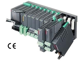
EXTERNAL VIEW
EXTERNAL DIMENSIONS & TERMINAL ASSIGNMENTS unit: mm (inch)