·Some details are not shown. Please refer to specification sheets for all information.
R1M-P4/MSR
PC Recorders R1M Series
PC RECORDER (4 totalized counter inputs, 8 contact inputs and outputs)
Functions & Features • Industrial recorder on PC • Totalized counter inputs • Counts stored in E2PROM • Easy system expansion via Modbus RTU • Recorded data exportable to spreadsheet applications
MODEL: R1M-P4T-[1][2]
ORDERING INFORMATION • Code number: R1M-P4T-[1][2] Specify a code from below for each [1] and [2]. (e.g. R1M-P4T-M2/MSR/Q) • Specify the specification for option code /Q (e.g. /C01)
FIELD TERMINAL TYPE T:M3 screw terminals
[1] POWER INPUT AC Power M2: 100 – 240 V AC (Operational voltage range 85 – 264 V, 47 – 66 Hz) DC Power R: 24 V DC (Operational voltage range 24 V ±10 %, ripple 10 %p-p max.)
[2] OPTIONS (multiple selections) PC Recorder Software Package (must be specified) /MSR: With Other Options blank: none /Q: Option other than the above (specify the specification)
SPECIFICATIONS OF OPTION: Q COATING (For the detail, refer to M-System's web site.) /C01: Silicone coating /C02: Polyurethane coating /C03: Rubber coating
PACKAGE INCLUDES... • PC Recorder Software CD • 9-pin D-sub connector, straight type (1 m or 3.3 ft)
GENERAL SPECIFICATIONS Connection Power input, transmission: Euro type connector terminal (Applicable wire size: 0.2 – 2.5 mm2 (AWG24 – 12), stripped length 7 mm) RS-232-C: 9-pin D-sub connector (male) (Lock screw No. 4-40 UNC) I/O: M3 screw terminals (torque: 0.6N·m) Screw terminal: Nickel-plated steel Housing material: Flame-resistant resin (gray) Channel selector for the digital display: Rotary DIP switch; 1 thr. 8: ch.1 thr. ch.8 contact input A thr. D: ch.A thr. ch.D totalized counter input 0, 9, E, F: no display Isolation: RS-232-C or RS-485 to I/O to power Node address setting: Rotary switch; 1 – F (15 nodes) RUN indicator LED: Green light blinks in normal conditions. Count memory at power loss: Count value is saved in the the non-volatile memory (E2PROM) when the power supply is lost. Number of rewritable times: 105 times Data storing characteristics: 10 years at 20°C ■ Indicators Digital display: 6-digit red LED; 4.6 mm high; Shows either totalized (lower 6 digits only) or momentary value; selectable with internal DIP switch
INPUT SPECIFICATIONS ■ Totalized Counter Input (high speed): Dry contact, 4 points Commons: All negatives Max. input frequency: 10 kHz Minimum pulse width: 50 μsec. Max. counter value: 999 999 999 (reset to zero at overflow) Sensing: Approx. 5 V DC (pull-up resistance 22 kΩ); ≤ 0.8 V at Lo; ≥ 4 V at Hi Caution: The totalized counter itself can accept frequencies as high as 10 kHz. In order to eliminate unwanted input by chattering, be careful to choose an input device to be free of the problem (e.g. mercury relay). ■ Contact Input: Dry contact, 8 points Commons: All negatives Sensing: Approx. 5 V DC (pull-up resistance 22 kΩ); ≤ 0.8 V at Lo; ≥ 4 V at Hi Sampling rate: 50 msec. Totalizing counter function Number of input channels: 8 Max. input frequency: 100 Hz Minimum pulse width: 5 msec. Max. counter value: 999 999 999 (reset to zero at overflow) ■ Counter Reset Input: Dry contact, 1 point Commons: All negatives Sensing: Approx. 5 V DC (pull-up resistance 22 kΩ); ≤ 0.8 V at Lo; ≥ 4 V at Hi Sampling rate: 50 msec. Logic: Enable at pulse edge sinking
OUTPUT SPECIFICATIONS ■ Contact Output: Open collector, 8 points Commons: All negatives Rating: 24 V DC @ 50 mA (resistive load) Saturation voltage: 1.6 V DC For use with inductive loads, external protection of contact and noise quenching is recommended. Sampling rate: 50 msec.
INSTALLATION Power consumption •AC: Approx. 10 VA •DC: Approx. 7 W Operating temperature: -5 to +60°C (23 to 140°F) Operating humidity: 30 to 90 %RH (non-condensing) Mounting: Surface or DIN rail Weight: 400 g (0.88 lb)
PERFORMANCE Multi-transmission time: 5 msec. Insulation resistance: ≥ 100 MΩ with 500 V DC Dielectric strength: 2000 V AC @ 1 minute (RS-232-C or RS-485 to I/O to power to ground)
PC RECORDER SOFTWARE PC Recorder Software Package (model: MSRPAC-2010) is included with purchases of this model. Refer to the MSRPAC-2010 data sheet for the contents of the package and the requirements for the PC to be prepared by the user.
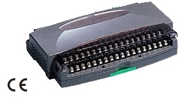
EXTERNAL VIEW
MODBUS WIRING CONNECTION
CONNECTION DIAGRAM
EXTERNAL DIMENSIONS & TERMINAL ASSIGNMENTS unit: mm (inch)