ORDERING INFORMATION • Code number: R3-DC16C[1][2] Specify a code from below for each of [1] and [2]. (e.g. R3-DC16CW/CE/Q) • Specify the specification for option code /Q (e.g. /C01)
NO. OF CHANNELS 16: 16
OUTPUT C: PNP transistor
[1] COMMUNICATION MODE S: Single W: Dual
[2] OPTIONS (multiple selections) Standards & Approvals blank: Without CE /CE: CE marking Other Options blank: none /Q: Option other than the above (specify the specification)
SPECIFICATIONS OF OPTION: Q COATING (For the detail, refer to M-System's web site.) /C01: Silicone coating /C02: Polyurethane coating /C03: Rubber coating
GENERAL SPECIFICATIONS Connection Internal bus: Via the Installation Base (model: R3-BSx) Output: M3 separable screw terminal (torque 0.5 N·m) Internal power: Via the Installation Base (model: R3-BSx) Screw terminal: Nickel-plated steel Isolation: Output to internal bus or internal power Output hold setting: Setting for communication error with side DIP SW RUN indicator: Bi-color (red/green) LED; Red when the bus A operates normally; Green when the bus B operates normally; Amber when both buses operate normally. ERR indicator: Green LED turns on in normal operating conditions. Output status indicator: Red LED; turns on with the output ON.
OUTPUT SPECIFICATIONS Output: Open collector, 16 points Isolation: Optical isolator Common: All 16 points (2 terminals) Common current: Max. 1.6 A per common External excitation: 24 V DC ±10% , approx. 0.02 A Rated load voltage: 24 V DC ±10 % Maximum load current: 0.1 A per point Maximum rush current: 0.5 A for max. 10 msec. Maximum leak current at OFF: 0.1 mA Maximum voltage drop at ON: 0.6 V DC typical; 1.2 V DC max. (When driving an inductive load, connect a diode in parallel with the load.)
INSTALLATION Operating temperature: -10 to +55°C (14 to 131°F) Operating humidity: 30 to 90 %RH (non-condensing) Atmosphere: No corrosive gas or heavy dust Mounting: Installation Base (model: R3-BSx) Weight: 200 g (0.44 lb)
PERFORMANCE Data allocation: 1 Current consumption: Approx. 100 mA Response time: ≤ 0.1 sec. Insulation resistance: ≥ 100 MΩ with 500 V DC Dielectric strength: 2000 V AC @ 1 minute (output to internal bus or internal power) 2000 V AC @ 1 minute (power input to FG; isolated on the power supply module)
STANDARDS & APPROVALS EU conformity: EMC Directive EMI EN 61000-6-4 EMS EN 61000-6-2 RoHS Directive EN 50581
FUNCTIONS ■OUTPUT HOLD or OUTPUT OFF In normal conditions, the module outputs the signal from the preferred bus A. When an error is detected, the output is switched to the data from the bus B. • Output Hold If both are in error, the module holds the signal and stands by until one of the communications recovers. • Output OFF If both are in error, the module outputs OFF signals and stands by until one of the communications recovers. At the startup, it outputs OFF until the communication is established and normal data is received.
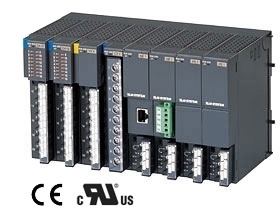
EXTERNAL VIEW
EXTERNAL DIMENSIONS & TERMINAL ASSIGNMENTS unit: mm (inch)