·Some details are not shown. Please refer to specification sheets for all information.
R1M-A1
Remote I/O R1M Series
CONTACT INPUT MODULE (contact input, 32 points)
Functions & Features • 32-point dry contact inputs • Easy system expansion via Modbus RTU
MODEL: R1M-A1[1]-[2][3]
ORDERING INFORMATION • Code number: R1M-A1[1]-[2][3] Specify a code from below for each [1] through [3]. (e.g. R1M-A1T-M2/Q) • Specify the specification for option code /Q (e.g. /C01)
[1] FIELD TERMINAL TYPE T:M3 screw terminals C1: FCN type connector (No CE conformance)
[2] POWER INPUT AC Power M2: 100 – 240 V AC (Operational voltage range 85 – 264 V, 47 – 66 Hz) DC Power R: 24 V DC (Operational voltage range 24 V ±10 %, ripple 10 %p-p max.)
[3] OPTIONS blank: none /Q: With options (specify the specification)
SPECIFICATIONS OF OPTION: Q COATING (For the detail, refer to M-System's web site.) /C01: Silicone coating /C02: Polyurethane coating /C03: Rubber coating
RELATED PRODUCTS • Connector terminal block (model: CNT) • Special cable (model: FCN32) • R1X configurator software (model: R1CON) Downloadable at M-System’s web site. A dedicated cable is required to connect the module to the PC. Please refer to the internet software download site or the users manual for the PC configurator for applicable cable types.
GENERAL SPECIFICATIONS Connection Power input, transmission: Euro type connector terminal (Applicable wire size AWG24-12 (0.2 – 2.5 mm2), stripped length 7 mm) RS-232-C: 9-pin D-sub connector (male) (Lock screw No. 4-40 UNC) Input: M3 screw terminals (torque: 0.6N·m) or FCN type connector (Fujitsu FCN-365P040-AU) Screw terminal: Nickel-plated steel Housing material: Flame-resistant resin (gray) Isolation: Input to RS-232-C or RS-485 to power Count memory at power loss: Count value is not saved when the power supply is lost. Node address setting: Rotary switch; 1 – F (15 nodes) RUN indicator LED: Green light blinks in normal conditions.
COMMUNICATION Baud rate: 38.4 kbps Communication: Half-duplex, asynchronous, no procedure Protocol: Modbus RTU Refer to Modbus Protocol Reference Guide (EM-5650) for supported functions. ■ RS-232-C Standard: Conforms to RS-232-C, EIA Transmission distance: 10 meters max. ■ RS-485 Standard: Conforms to TIA/EIA-485-A Transmission distance: 500 meters max. Transmission media: Shielded twisted-pair cable (CPEV-S 0.9 dia.)
INPUT SPECIFICATIONS Input: Dry contact, 32 points Commons: All negatives Sensing: Approx. 5 V DC (pull-up resistance 22 kΩ) ≤ 1.5 V at ON ≥ 4 V at OFF Sampling rate: 50 msec. • Totalizing Counter Function Number of input channels: 16 (ch.1 thr. 16 available both with instantaneous status and totalized value) Max. input frequency: 100 Hz Minimum pulse width: 5 ms Counter reset input: Pulse rising (ch.32 assigned) Max. counter value: 999 999 999 (reset to zero at overflow)
INSTALLATION Power consumption •AC: Approx. 10 VA •DC: Approx. 7 W Operating temperature: -5 to +60°C (23 to 140°F) Operating humidity: 30 to 90 %RH (non-condensing) Mounting: Surface or DIN rail Weight: 400 g (0.88 lb)
PERFORMANCE Multi-transmission time: 5 msec. Insulation resistance: ≥ 100 MΩ with 500 V DC Dielectric strength: 2000 V AC @ 1 minute (input to RS-232-C or RS-485 to power to FG)
STANDARDS & APPROVALS EU conformity: EMC Directive EMI EN 61000-6-4 EMS EN 61000-6-2 Low Voltage Directive EN 61010-1, EN 61010-2-201 Installation Category II Pollution Degree 2 Input or RS-232-C/RS-485 to power: Reinforced insulation (300 V) Input to RS-232-C/RS-485: Basic insulation (300 V) RoHS Directive EN 50581
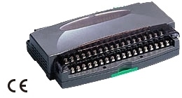
EXTERNAL VIEW
MODBUS WIRING CONNECTION
CONNECTION DIAGRAM Note: In order to improve EMC performance, bond the FG terminal to ground. Caution: FG terminal is NOT a protective conductor terminal.
MODBUS COMMUNICATION
EXTERNAL DIMENSIONS & TERMINAL ASSIGNMENTS unit: mm (inch)