·Some details are not shown. Please refer to specification sheets for all information.
R3-NE1
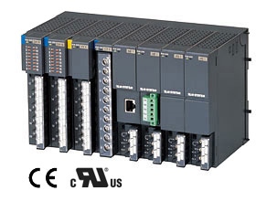
Remote I/O R3 Series
ETHERNET INTERFACE MODULE (Modbus/TCP)
MODEL: R3-NE1-[1][2]
ORDERING INFORMATION • Code number: R3-NE1-[1][2] Specify a code from below for each of [1] and [2]. (e.g. R3-NE1-R/CE/Q) • Specify the specification for option code /Q (e.g. /C01/SET)
[1] POWER INPUT N: No power supply (Use with Ver.2.00 or higher versions of Power Supply Module (model: R3-PSx) to conform with CE marking.) AC Power K3: 100 – 120 V AC (Operational voltage range 85 - 132 V, 47 - 66 Hz) * (CE not available) L3: 200 – 240 V AC (Operational voltage range 170 - 264 V, 47 - 66 Hz) * (CE not available) DC Power R: 24 V DC (Operational voltage range 24 V ±10 %, ripple 10 %p-p max.) * * Not selectable for use with independent power modules or network modules with the internal power input options.
[2] OPTIONS (multiple selections) Standards & Approvals blank: Without CE /CE: CE marking Other Options blank: none /Q: Option other than the above (specify the specification)
SPECIFICATIONS OF OPTION: Q (multiple selections) COATING (For the detail, refer to M-System's web site.) /C01: Silicone coating /C02: Polyurethane coating /C03: Rubber coating EX-FACTORY SETTING /SET: Preset according to the Ordering Information Sheet (No. ESU-8361)
RELATED PRODUCTS • PC configurator software (model: R3CON) Downloadable at M-System’s web site. A dedicated cable is required to connect the module to the PC. Please refer to the internet software download site or the users manual for the PC configurator for applicable cable types.
GENERAL SPECIFICATIONS Connection Ethernet: RJ-45 connector Internal bus: Via the Installation Base (model: R3-BSx) Internal power: Via the Installation Base (model: R3-BSx) Power input, RUN contact output: M3 separable screw terminal (torque 0.5 N·m) Screw terminal: Nickel-plated steel Isolation: Ethernet to internal bus or internal power to power supply to RUN contact output to FG Input error data setting: Input value setting at input module error with side DIP SW Dual communication setting: Set with the side DIP switch Data allocation setting: Set with the side DIP switch RUN indicator: Bi-color (green/red) LED; Green ON in normal communication; Red ON when receiving data (Function selected with DIP SW) ERR indicator: Bi-color (green/red) LED; Green ON or blinking at communication error; Red ON at transmitting data (Function selected with DIP SW) ■ RUN CONTACT OUTPUT RUN contact: Turns ON while the green RUN LED is ON (Ethernet in normal communication). Rated load: 250 V AC @ 0.5 A (cos ø = 1) 30 V DC @ 0.5 A (resistive load) (Less than 50 V AC to conform with EU Directive) Maximum switching voltage: 250 V AC or 30 V DC Maximum switching power: 250 VA or 150 W Minimum load: 1 V DC @ 1 mA Mechanical life: 2 × 10⁷ cycles (300 cycles/min.) When driving an inductive load, external contact protection and noise quenching recommended.
ETHERNET COMMUNICATION Communication Standard: IEEE 802.3u Transmission: 10BASE-T, 100BASE-TX Baud rate: 10/100 Mbps (Auto Negotiation function) Protocol: Modbus/TCP Data: RTU (Binary) Max. number of socket connections: 2 Transmission media: 10BASE-T (STP, Category 5) 100BASE-TX (STP, Category 5e) Max. length of fieldbus segment: 100 meters Ethernet indicator LED: LINK, DPLX, LINK10, LINK100, COL IP address: 192.168.0.1 (factory setting); Selectable with PC Configurator Software (model: R3CON) Port No.: 502
INSTALLATION Power consumption •AC:Approx. 20 VA •DC: Approx. 12 W Current consumption (no power supply): 100 mA Output current (power supply): 250 mA continuous at 20 V DC; 400 mA for 10 minutes Operating temperature: -10 to +55°C (14 to 131°F) Operating humidity: 30 to 90 %RH (non-condensing) Atmosphere: No corrosive gas or heavy dust Mounting: Installation Base (model: R3-BSx) Weight: 200 g (0.44 lb)
PERFORMANCE Insulation resistance: ≥ 100 MΩ with 500 V DC Dielectric strength: 1500 V AC @ 1 minute (Ethernet to internal bus or internal power to power input to RUN contact output to FG)
STANDARDS & APPROVALS EU conformity: EMC Directive EMI EN 61000-6-4 EMS EN 61000-6-2 RoHS Directive EN 50581
EXTERNAL VIEW
MODBUS FUNCTION CODES & SUPPORTED CODES
MODBUS I/O ASSIGNMENT
TRANSMISSION DATA DESCRIPTIONS
MODULE STATUS, ERROR STATUS, DATA ERROR STATUS
I/O DATA DESCRIPTIONS The data allocations for typical I/O modules are shown below. Refer to the manual for each module for detailed data allocations.
EXTERNAL DIMENSIONS & TERMINAL ASSIGNMENTS unit: mm (inch)
SCHEMATIC CIRCUITRY & CONNECTION DIAGRAM Note: In order to improve EMC performance, bond the FG terminal to ground. Caution: FG terminal is NOT a protective conductor terminal.