·Some details are not shown. Please refer to specification sheets for all information.
R3-MS4
Remote I/O R3 Series
POTENTIOMETER INPUT MODULE (4 points, isolated)
MODEL: R3-MS4[1][2]
ORDERING INFORMATION • Code number: R3-MS4[1][2] Specify a code from below for each of [1] and [2]. (e.g. R3-MS4W/CE/Q) • Specify the specification for option code /Q (e.g. /C01/SET)
INPUT Total resistance 100 Ω - 20 kΩ
NO. OF CHANNELS 4: 4
[1] COMMUNICATION MODE S: Single W: Dual
[2] OPTIONS (multiple selections) Standards & Approvals blank: Without CE /CE: CE marking Other Options blank: none /Q: Option other than the above (specify the specification)
SPECIFICATIONS OF OPTION: Q (multiple selections) COATING (For the detail, refer to M-System's web site.) /C01: Silicone coating /C02: Polyurethane coating /C03: Rubber coating EX-FACTORY SETTING /SET: Preset according to the Ordering Information Sheet (No. ESU-8401)
GENERAL SPECIFICATIONS Connection Internal bus: Via the Installation Base (model: R3-BSx) Input: M3 separable screw terminal (torque 0.5 N·m) Internal power: Via the Installation Base (model: R3-BSx) Screw terminal: Nickel-plated steel Isolation: Input 1 to input 2 to input 3 to input 4 to internal bus or internal power Conversion rate: Selectable with the side DIP SW RUN indicator: Bi-color (red/green) LED; Red when the bus A operates normally; Green when the bus B operates normally; Amber when both buses operate normally. ERR indicator: Bi-color (red/green) LED; Red with input abnormality; Green in normal operating conditions.
INPUT SPECIFICATIONS Minimum span: 50 % of total resistance Excitation: Approx. 0.2 V DC
INSTALLATION Operating temperature: -10 to +55°C (14 to 131°F) Operating humidity: 30 to 90 %RH (non-condensing) Atmosphere: No corrosive gas or heavy dust Mounting: Installation Base (model: R3-BSx) Weight: 200 g (0.44 lb)
PERFORMANCE Conversion accuracy: Refer to the table at the end of this section. The resolution and conversion accuracy are defined against the potentiometer's total resistance. If the actual resistance range (between the zero and span positions) is narrower than the total resistance, the values change in proportion. Using at least 50 % of the total resistance is basically recommended. Conversion rate: 80 / 40 / 20 / 10 msec. selectable Data range: 0 – 10000 Data allocation: 4 Current consumption: Approx. 50 mA Temp. coefficient: ±0.015 % /°C Temperature coefficient is defined against the potentiometer's total resistance. If the actual resistance range (between the zero and span positions) is narrower than the total resistance, the values change in proportion. Using at least 50 % of the total resistance is basically recommended. Insulation resistance: ≥ 100 MΩ with 500 V DC Dielectric strength: 2000 V AC @ 1 minute (input 1 to input 2 to input 3 to input 4 to internal bus or internal power) 2000 V AC @ 1 minute (power input to FG; isolated on the power supply module)
STANDARDS & APPROVALS EU conformity: EMC Directive EMI EN 61000-6-4 EMS EN 61000-6-2 RoHS Directive EN 50581
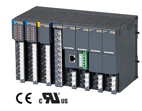
EXTERNAL VIEW
EXTERNAL DIMENSIONS & TERMINAL ASSIGNMENTS unit: mm (inch)