Functions & Features • 16 points relay contact output module for Modbus/TCP (Ethernet)
MODEL: R7K4FE-6-DC16-R[1]
ORDERING INFORMATION • Code number: R7K4FE-6-DC16-R[1] Specify a code from below for [1]. (e.g. R7K4FE-6-DC16-R/Q) • Specify the specification for option code /Q (e.g. /C01)
TERMINAL BLOCK 6: Screw terminal block for power supply RJ-45 Modular jack for communication Screw terminal block for I/O
I/O TYPE DC16: Relay contact output, 16 points
POWER INPUT DC power R: 24 V DC (Operational voltage range: ±10 %; ripple 10 %p-p max.)
[1] OPTIONS blank: none /Q: With options (specify the specification)
SPECIFICATIONS OF OPTION: Q COATING (For the detail, refer to M-System's web site.) /C01: Silicone coating /C02: Polyurethane coating /C03: Rubber coating
GENERAL SPECIFICATIONS Connection Ethernet: RJ-45 Modular Jack Power input, output: M3 separable screw terminal (torque 0.5 N·m) Solderless terminal: Refer to the drawing at the end of the section. Recommended manufacturer: Japan Solderless Terminal MFG.Co.Ltd, Nichifu Co.,ltd Applicable wire size: 0.25 to 1.65 mm2 (AWG 22 to 16) Screw terminal: Nickel-plated steel Housing material: Flame-resistant resin (gray) Isolation: Output 0 to output 1 to output 2 to output 3 to output 4 to output 5 to output 6 to output 7 to output 8 to output 9 to output 10 to output 11 to output 12 to output 13 to output 14 to output 15 to Ethernet or FE to power Output at the loss of communication: Output hold(*), Output clear Selectable with the front DIP SW (*) factory default setting Indicator LEDs: PWR, ERR indicate the module’s operating conditions. (Refer to the insruction manual) Discrete output indicator LEDs: Green LED; turns on with output ON
ETHERNET COMMUNICATION Communication Standard: IEEE 802.3u Transmission: 10BASE-T, 100BASE-TX Baud rate: 10/100 Mbps (Auto Negotiation function) Protocol: Modbus/TCP Data: RTU (Binary) Max. number of socket connections: 2 Transmission media: 10BASE-T (STP, Category 5) 100BASE-TX (STP, Category 5e) Max. length of fieldbus segment: 100 meters IP address: 192.168.0.1 (factory setting); Selectable with PC Configurator Software (model: R7CFG) Port No.: 502 Ethernet indicator LED: Link, Link100, COL (Refer to the insruction manual)
OUTPUT SPECIFICATIONS Common: 1 common per 1 point (16 points) Maximum load current: 2.0 A per point Maximum outputs applicable at once: No limit (at 24 V DC) Output supply voltage/current: 24V DC±10%/≥ 120mA Rated load: 250 V AC @ 2A, 30 V DC @ 2A Maximum switching voltage: 250 V AC, 30 V DC Maximum switching power: 500 VA (AC), 60 W (DC) Minimum applicable load: 5 V DC @ 1 mA Mechanical life: 2 × 10⁷ cycles (300 cycles per min.) When driving an inductive load, external contact protection and noise quenching recommended. ON delay time: ≤ 10 msec. OFF delay time: ≤ 10 msec.
INSTALLATION Current consumption •DC: Approx. 130 mA (contact output load charge is not included) Operating temperature: -10 to +55°C (14 to 131°F) Storage temperature: -20 to +65°C (-4 to +149°F) Operating humidity: 30 to 90 %RH (non-condensing) Atmosphere: No corrosive gas or heavy dust Mounting: Surface or DIN rail (35 mm rail) Weight: 330 g (0.73 lb)
PERFORMANCE Insulation resistance: ≥ 100 MΩ with 500 V DC Dielectric strength: 1500 V AC @ 1 minute(Output 0 to output 1 to output 2 to output 3 to output 4 to output 5 to output 6 to output 7 to output 8 to output 9 to output 10 to output 11 to output 12 to output 13 to output 14 to output 15 to Ethernet or FE to power)
STANDARDS & APPROVALS EU conformity: EMC Directive EMI EN 61000-6-4 EMS EN 61000-6-2 Low Voltage Directive EN 61010-1,EN 61010-2-201 Measurement Category II (output) Pollution Degree 2 Output to power: Basic insulation (250 V) RoHS Directive EN 50581
PC CONFIGURATOR The following parameters can be set with using PC Configurator Software (model: R7CFG) Refer to the users manual for the R7CFG for detailed operation of the software program.
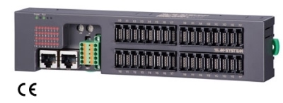
EXTERNAL VIEW
TERMINAL ASSIGNMENTS
MODBUS FUNCTION CODES & SUPPORTED CODES
MODBUS I/O ASSIGNMENT
I/O DATA DESCRIPTIONS
EXTERNAL DIMENSIONS & TERMINAL ASSIGNMENTS unit: mm (inch)
MOUNTING REQUIREMENTS unit: mm (inch)
SCHEMATIC CIRCUITRY & CONNECTION DIAGRAM Note: In order to improve EMC performance, bond the FE terminal to ground. Caution: FE terminal is NOT a protective conductor terminal.