·Some details are not shown. Please refer to specification sheets for all information.
R8-SS2
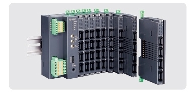
Remote I/O R8 Series
DC CURRENT INPUT MODULE (2 points, isolated)
Functions & Features • 2 channels for DC current input, compact size remote I/O module • Isolation between channels • Input range adjustment with DIP switch or PC configurator
MODEL: R8–SS2[1]
ORDERING INFORMATION • Code number: R8-SS2[1] Specify a code from below for [1]. (e.g. R8-SS2/Q) • Specify the specification for option code /Q (e.g. /C01)
[1] OPTIONS blank: none /Q: With options (specify the specification)
SPECIFICATIONS OF OPTION: Q COATING (For the detail, refer to M-System's web site.) /C01: Silicone coating /C02: Polyurethane coating
RELATED PRODUCTS • PC configurator software (model: R8CFG) Downloadable at M-System’s web site. A dedicated cable is required to connect the module to the PC. Please refer to the internet software download site or the users manual for the PC configurator for applicable cable types.
GENERAL SPECIFICATIONS Connection •Input: 4-pin e-CON connector PWB connector XN2D-1474-S002 (Omron) Recommended cable connector XN2A-1470 (Omron) Applicable wire size 0.08 mm2 (AWG28) - 0.5 mm2 (AWG20) Outer sheath diameter: max. 1.5 dia (The cable connector is not included in the package. Refer to the specifications of the product.) •Excitation supply, internal bus: Connected to internal bus connector •Internal power: Supplied from internal bus connector Isolation: Input 1 to input 2 to exc. supply to internal bus or internal power Input range: Selectable with the side DIP SW Module address: With rotary switch Terminating resistor: Built-in (DIP Switch, default: disable) Configuration mode: With DIP switches on the side panel Status indicator: Bi-color (red/green) LED; Refer to the instruction manual. Input status indicators: Red LED; Refer to the instruction manual.
INPUT Input range: -20 – +20 mA DC configurable Input range: :-5 - +105 % (in percentage of input range) Input resistance: 100 Ω
INSTALLATION Max. current consumption: 100 mA Operating temperature: -10 to +55°C (14 to 131°F) Operating humidity: 30 to 90 %RH (non-condensing) Atmosphere: No corrosive gas or heavy dust Mounting: DIN rail Weight: 60 g (2.12 oz)
PERFORMANCE Conversion accuracy(in percentage of input range) ±0.1 % (@ input range -20 - +20 mA) Conversion accuracy is inversely proportional to input span. Conversion accuracy computation example: When input range is 4 - 20 mA: conversion accuracy = nominal input span (40 mA) ÷ input span (16 mA) × 0.1(%) = 0.25 (%). Nominal input span is the same as the span at input range -20 - +20 mA DC. Conversion rate: 2 msec. Input circuit time constant: Approx. 1 msec. Data range: 0 – 10000 of the input range Data allocation: 2 Module addresses in use: 1 Max. consumption current: 100 mA Temp. coefficient: ±0.015 %/°C (±0.008 %/°F) Insulation resistance: ≥ 100 MΩ with 500 V DC Dielectric strength: 1000 V AC @ 1 minute (input 1 to input 2 to exc. supply to internal bus or internal power to FG) 1000 V AC @ 1 minute (for modules combined with this device)
STANDARDS & APPROVALS EU conformity: EMC Directive EMI EN 61000-6-4 EMS EN 61000-6-2 RoHS Directive EN 50581
EXTERNAL VIEW
OPERATING MODE SETTING
(*) Factory setting Caution ! - SW4-3 through 4-7 are unused. Be sure to turn off unused ones.