·Some details are not shown. Please refer to specification sheets for all information.
R30CT4E
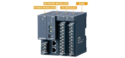
Remote I/O R30 Series
AC CURRENT INPUT MODULE (4 points, isolated, clamp-on current sensor type CLSE use)
Functions & Features • 4 channels AC current input remote I/O module • Isolation between input channels • Input range of each channel is individually adjustable with PC configurator
MODEL: R30CT4ES[1]
ORDERING INFORMATION • Code number: R30CT4ES[1] Specify a code from below for [1]. (e.g. R30CT4ES/Q) • Specify the specification for option code /Q (e.g. /C01/SET)
NO. OF CHANNELS 4E: 4 channels, Sensor type CLSE
COMMUNICATION MODE S: Single
[1] OPTIONS blank: none /Q: With options (specify the specification)
SPECIFICATIONS OF OPTION: Q (multiple selections) COATING (For the detail, refer to M-System's web site.) /C01: Silicone coating /C02: Polyurethane coating /C03: Rubber coating EX-FACTORY SETTING /SET: Preset according to the Ordering Information Sheet (No. ESU-9018)
RELATED PRODUCTS • PC configurator software (model: R30CFG) Downloadable at M-System’s web site. For connecting to PC, use commercially available Mini-B type USB cable. (provided by user) • Clamp-on current sensor (model: CLSE) The clamp-on current sensors, not included in this product package, must be ordered separately. Required number depends upon the system configuration.
GENERAL SPECIFICATIONS Connection Internal bus: Via the Installation Base (model: R30BS) Input: M3 separable screw terminal (torque 0.5 N·m) Internal power supply: Via the Installation Base (model: R30BS) Solderless terminal: Refer to the drawing at the end of the section. Recommended manufacturer: Japan Solderless Terminal MFG. Co., Ltd., Nichifu Co., Ltd. (Solderless terminals with insulation sleeve do not fit.) Applicable wire size: 0.25 to 0.75 mm2 Screw terminal: Nickel-plated steel Isolation: Input 1 to input 2 to input 3 to input 4 to internal bus or internal power Input range: Selectable with PC configuration software (model: R30CFG) Conversion rate: Selectable with PC configuration software (model: R30CFG) Status indicator LED: RUN, ERR (refer to the instruction manual) Low-end cutout: Converted as 0 % for the input below setting value (0.5 - 50 %).
INPUT SPECIFICATIONS Module type: Analog input, 4 points Sensors (Not included in the package) CLSE-R5: 0 – 5 A CLSE-05: 0 – 50 A CLSE-10: 0 – 100 A CLSE-20: 0 – 200 A CLSE-40: 0 – 400 A CLSE-60: 0 – 600 A Frequency: 50 / 60 Hz common use (45 - 65 Hz) Operational range: 5 – 115 % of rating Overload capacity: 120 % of rating (continuous) Be sure that the input voltage is of 480 V or less.
INSTALLATION Current consumption: 45 mA max. Operating temperature: -10 to +55°C (14 to 131°F) Storage temperature: -20 to +65°C (-4 to +149°F) Operating humidity: 10 to 90 %RH (non-condensing) Atmosphere: No corrosive gas or heavy dust Mounting: Installation Base (model: R30BS) Weight: 160 g (0.35 lb)
PERFORMANCE Conversion rate / conversion accuracy: 10 ms / ±2.0%, 20 ms / ±1.0%, 40 ms / ±0.5%, 80 ms / ±0.5% (*) (*) Factory setting (Conversion accuracy is the value within operational input range. The sensor accuracy is not included in the conversion rate) Input circuit time constant: 300 msec. Data range: Engineering unit value (A) × 100 (integer) (For CLSE-R5, engineering unit value (A) × 1000 (integer)) Data allocation: 4 Temp. coefficient: ±0.015 %/°C (±0.008 %/°F) Insulation resistance: ≥ 100 MΩ with 500 V DC Dielectric strength: 1500 V AC @ 1 minute (input 1 to input 2 to input 3 to input 4 to internal bus or internal power) 1500 V AC @ 1 minute (power input to FE; isolated on the power supply module)
STANDARDS & APPROVALS EU conformity: EMC Directive EMI EN 61000-6-4 EMS EN 61000-6-2 RoHS Directive EN 50581
PC CONFIGURATOR The following parameters can be set with using PC Configurator Software (model: R30CFG) Refer to the users manual for the R30CFG for detailed operation of the software program.
EXTERNAL VIEW
TERMINAL ASSIGNMENTS
EXTERNAL DIMENSIONS & TERMINAL ASSIGNMENTS unit: mm (inch)