·Some details are not shown. Please refer to specification sheets for all information.
R5-ND2
Remote I/O R5 Series
DeviceNet INTERFACE MODULE (for 32-point analog signals)
MODEL: R5-ND2[1]
ORDERING INFORMATION • Code number: R5-ND2[1] Specify a code from below for [1]. (e.g. R5-ND2/Q) • Specify the specification for option code /Q (e.g. /C01)
[1] OPTIONS blank: none /Q: With options (specify the specification)
SPECIFICATIONS OF OPTION: Q COATING (For the detail, refer to M-System's web site.) /C01: Silicone coating /C02: Polyurethane coating /C03: Rubber coating
RELATED PRODUCTS • PC configurator software (model: R5CON) • EDS file The EDS file and configurator software are downloadable at M-System’s web site. A dedicated cable is required to connect the module to the PC. Please refer to the internet software download site or the users manual for the PC configurator for applicable cable types.
GENERAL SPECIFICATIONS Connection DeviceNet: Euro type connector terminal (Applicable wire size: 0.2 – 2.5 mm2 (AWG 24 to 12), stripped length 7 mm) Internal bus: Via the Installation Base (model: R5-BS) Internal power: Via the base (model: R5-BS) Isolation: DeviceNet to internal bus or internal power Data allocation: Fixed to Mode 2
DeviceNet COMMUNICATION Transmission cable: Approved for DeviceNet Node address setting: DIP switch; 00 – 63 Baud rate: 125 kbps, 250 kbps, 500 kbps DIP switch NS (Network Status) indicator: Bi-color (green/red) LED indicates status of the communication link. MS (Module Status) indicator: Bi-color (green/red) LED indicates device status. Data allocation: 32 words for input data 35 words for output data
INSTALLATION Supply voltage to network: 11 – 25 V DC supplied through the network terminal block Supply current to network: 50 mA max. Operating temperature: -10 to +55°C (14 to 131°F) Operating humidity: 30 to 90 %RH (non-condensing) Atmosphere: No corrosive gas or heavy dust Mounting: Installation Base (model: R5-BS) Weight: 100 g (3.53 oz)
PERFORMANCE Insulation resistance: ≥ 100 MΩ with 500 V DC Dielectric strength: 2000 V AC @ 1 minute (DeviceNet to internal bus or internal power)
STANDARDS & APPROVALS EU conformity: EMC Directive EMI EN 61000-6-4 EMS EN 61000-6-2 RoHS Directive EN 50581
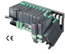
EXTERNAL VIEW
TRANSMISSION DATA DESCRIPTIONS The DIP SW located at the side of the module must be turned OFF. Data Allogcation Mode 2 is used for the R5-ND2. In this mode, two (2) words are assigned for one I/O module regardless of whether the second word area is required or not. For example, discrete I/O modules require only one (1) word, but two (2) words are automatically assigned to these modules. ■ I/O CAPACITY A maximum of 16 I/O modules can be mounted per node.
I/O DATA DESCRIPTIONS The data allocations for typical I/O modules are shown below. Refer to the manual for each module for detailed data allocations.